Anti-stripping pipe clamp

A pipe clamp and anti-dropping technology, which is applied in the direction of pipe supports, pipes/pipe joints/pipe fittings, connecting components, etc., can solve the problems of low assembly efficiency, occupying space for transportation and placement, and loss of elastic expansion characteristics, etc., to achieve simple structure, Easy to use and guarantee the effect of integration

Active Publication Date: 2015-07-08
黄山市必利精密塑业科技有限公司
View PDF4 Cites 0 Cited by
  • Summary
  • Abstract
  • Description
  • Claims
  • Application Information

AI Technical Summary

Problems solved by technology

When the above-mentioned structure is in use, its own disadvantages gradually appear: due to the integrated structure between the jaw and the insertion column, the small expansion pin is isolated. On the one hand, it often leads to the need to Shipping and storage in separate boxes takes up a lot of transportation and storage space, resulting in a significant increase in its transportation and site costs; Low assembly efficiency
Some manufacturers also discovered the above problems during production, and began to put the expansion pins into the insertion columns to form an assembly to realize the overall boxing; however, because the expansion pins themselves have a cylindrical structure with the same diameter , if the insertion depth of the expansion pin is too shallow, during actual handling, the expansion pin will often slide off from the insertion column due to the bumping of the vehicle body or other factors; It is always in an inflated state, making it lose its elastic expansion characteristics in the subsequent assembly process, which ultimately affects its assembly efficiency and stability, thus causing great trouble to the staff

Method used


Image

  • Anti-stripping pipe clamp
  • Anti-stripping pipe clamp
  • Anti-stripping pipe clamp

Examples


Embodiment Construction

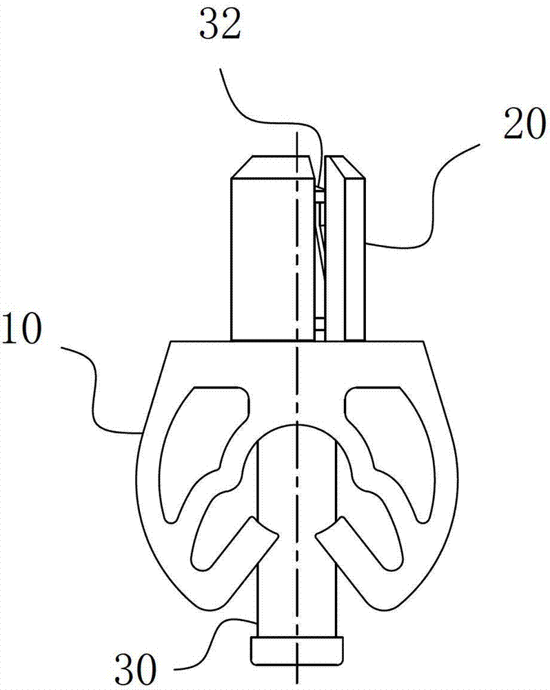
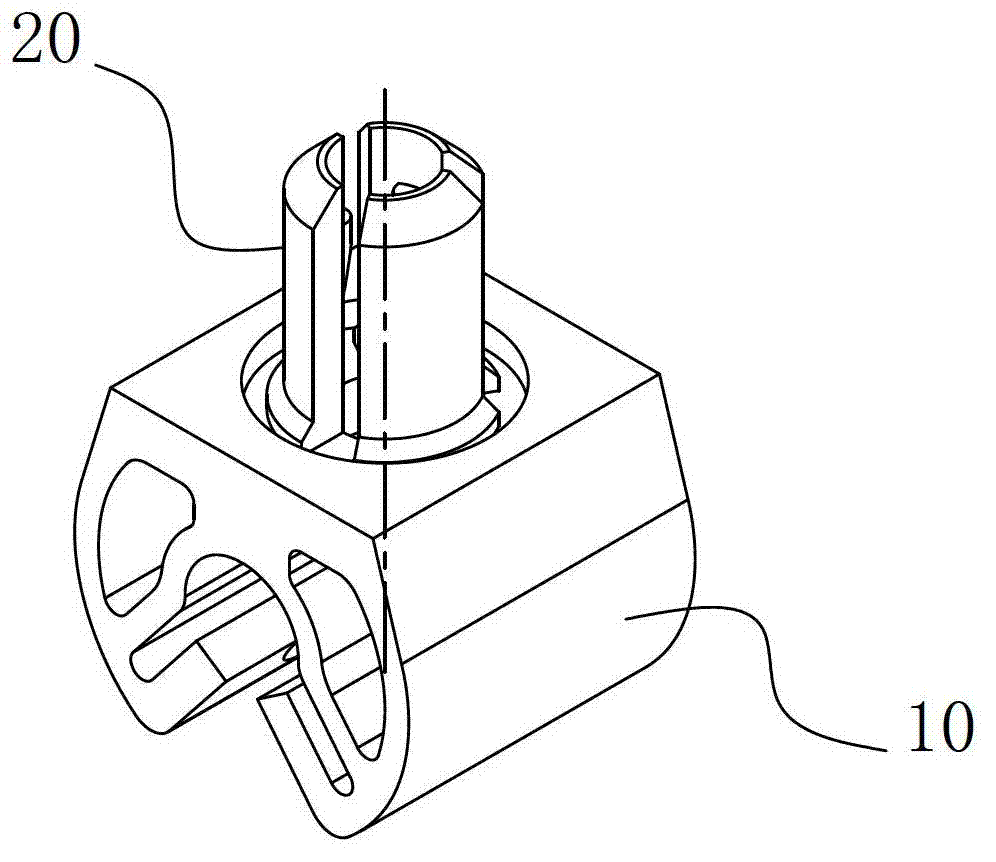
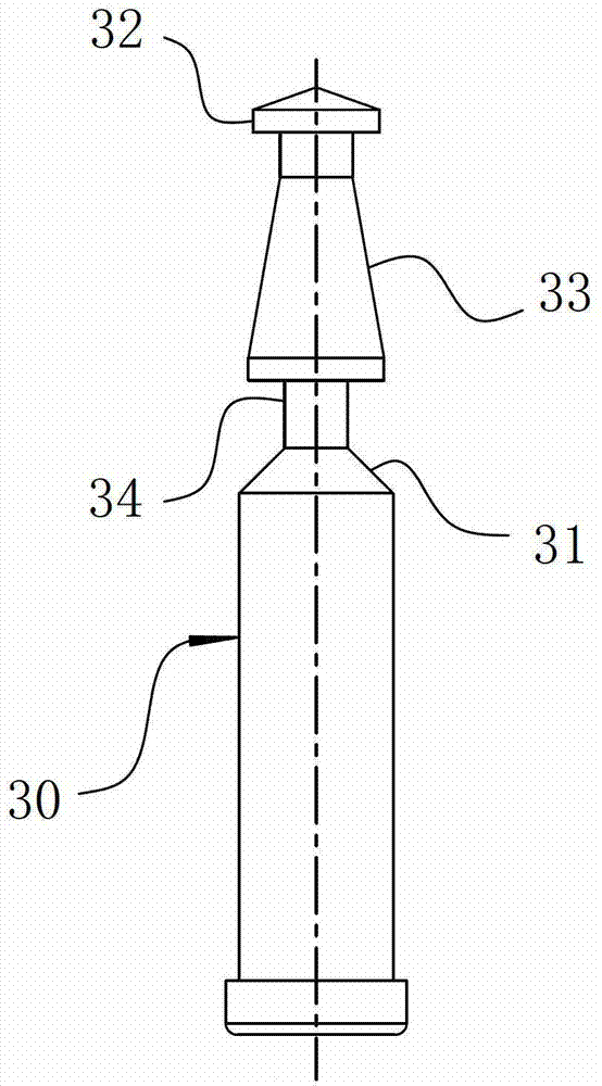
[0010] An anti-loosening pipe clamp, including a clamp mouth 10 for clamping pipe fittings, and the other side of the clamp mouth 10 is opposite to the clamping interface A for clamping pipe fittings. A positive tapered through hole 21 that penetrates the plug post 20 is arranged along its axis from its top end to its root. The through hole 21 constitutes the hollow expansion sleeve structure of the plug post 20 and the plug post 20 and A plug-in expansion nail is formed between the fixing parts of the vehicle body. The pipe clamp also includes an expansion pin 30 for forming a plug-in fit with the expansion sleeve-like plug-in column 20. The plug-in end 31 on the expansion pin 30 is A gear part 32 is arranged forward along its axis. The gear part 32 forms a one-way gear fit with the top end of the insertion post 20. The distance between the gear part 32 on the expansion pin 30 and its insertion end 31 is greater than or equal to the length of the through hole 21 .

[0011] I...


PUM


Abstract

The invention belongs to the field of automobile connecting pieces, specifically relates to an anti-stripping pipe clamp. The anti-stripping pipe clamp comprises a nip used for clamping pipe fittings. The other side of the nip relative to a clamping interface used for clamping pipe fittings is reversely provided with inserting columns orderly. Each inserting column is distributed with right tapered through holes penetrating the inserting column. The through holes form a hollow expansive sleeve structure of the inserting column, and the inserting columns and automobile fixing pieces form an inserting type expansive nail match. The pipe clamp also comprises expansive pins used for forming an inserting match with the inserting columns which are in a shape of an expansive sleeve. The inserting ends of the expansive pins are forwardly provided with sheltering sections orderly along the axes. The sheltering sections and the top ends of the inserting columns form a unidirectional sheltering match. The separation distances of the sheltering sections on the expansive pins and the inserting ends are greater than or equal to the lengths of the through holes. The unidirectional stop performance is realized after the expansive pins are inserted in the inserting columns by arranging the sheltering sections at the inserting ends of the expansive pins, so that the storage and transportation cost of the pipe clamp is obviously reduced, and meanwhile the self-working performance of the pipe clamp is maintained.

Description

technical field [0001] The invention belongs to the field of automobile connectors, and in particular relates to an anti-loosening pipe clip. Background technique [0002] The pipe clamp is a fixing device for fixing the oil pipe or other pipe fittings to the vehicle body or a relatively fixed position. When in use, one end is fixed at the fixed position of the vehicle body, and the other end is clamped on the automobile oil pipe or other pipe fittings to implement the purpose of fixing oil pipes and other pipe fittings. At present, the commonly used pipe clamp structure usually includes a jaw with a "Ω" structure. The opening end of the jaw forms a clamping interface that snaps onto the outer wall of the pipe. The middle of the other end of the jaw is opposite to the position of the opening end. An insertion column for inserting the body fixing parts is arranged in succession, and the insertion column is a hollow expansion sleeve structure. Of course, the pipe clamp also i...

Claims


Application Information

Patent Timeline
Patent Type & Authority Patents(China)
IPC IPC(8): F16L3/00F16B13/06
Inventor 陶华丽
Owner 黄山市必利精密塑业科技有限公司
Why Eureka
Try Eureka