
Part grabbing device for automatic production workshop

A technology for grabbing devices and production workshops, which is applied to conveyor objects, transportation and packaging, and metal processing. It can solve the problems of heavy labor burden, low work efficiency, and inability to protect parts, so as to reduce the labor burden of workers and improve Production quality, improve assembly efficiency low effect

Pending Publication Date: 2021-11-05
CHANGZHOU INST OF MECHATRONIC TECH
View PDF9 Cites 1 Cited by
  • Summary
  • Abstract
  • Description
  • Claims
  • Application Information

AI Technical Summary

Problems solved by technology

[0002] In the machining process, a large number of precision mechanical parts are operated and processed, and the parts need to be moved manually during the processing. A large amount of work increases the waste of labor, and the work efficiency is low. Grabbing and moving, the existing grabbing device cannot protect the parts when grabbing the parts, which is easy to cause damage to the parts and affects the production quality. In addition, the opening direction of the existing grabbing devices is fixed, so it is impossible to protect the parts. It is inconvenient to use and has a single function to do flipping and turning. When many parts are assembled to the parts, they are generally assembled manually. However, the orientation of the parts needs to be accurately changed during the assembly process to adapt to the assembly of parts at different angles. , the efficiency of manual assembly is low, and the labor burden of workers is heavy

Method used


Image

  • Part grabbing device for automatic production workshop
  • Part grabbing device for automatic production workshop
  • Part grabbing device for automatic production workshop

Examples


Embodiment Construction

[0026] The technical solutions in the embodiments of the present invention will be clearly and completely described below in conjunction with the drawings in the embodiments of the present invention.

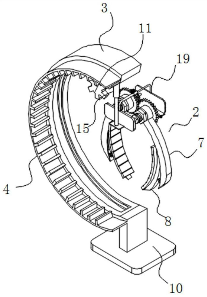
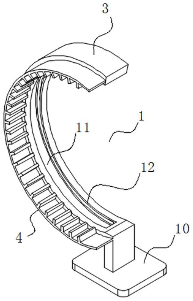
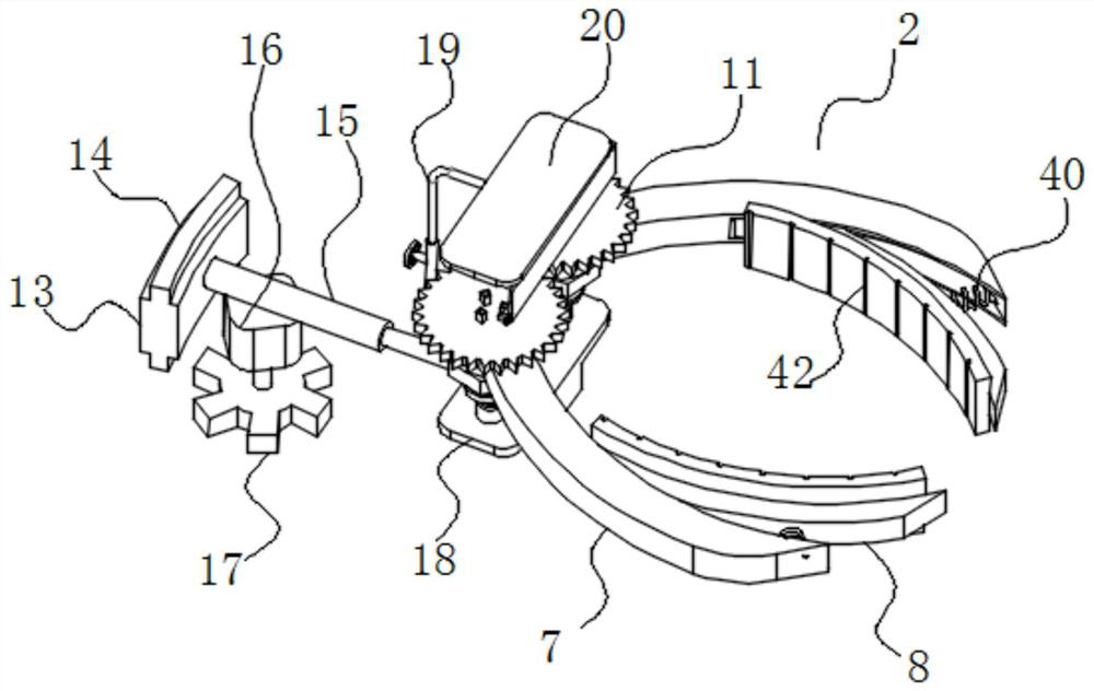
[0027] see Figure 1-8 Description of this embodiment, a parts grabbing device for an automated production workshop, which includes a support frame 1 and a grabbing assembly 2, the grabbing assembly 2 is connected to the support frame 1 by sliding fit, the support frame 1 includes an arc-shaped connecting plate 3, and the arc The side of the shaped connecting plate 3 is fixedly connected with an arc-shaped gear bar 4, and the grasping assembly 2 includes a sliding frame 5, a rotating part 6, a first claw 7 and a second claw 8, and one end of the rotating part 6 is connected to the sliding frame 5 in rotation. , the other end of the rotating part 6 is engaged and connected with the sliding frame 5, the first claw 7 is connected with the rotating part 6, the first claw 7 is connec...


PUM


Abstract

The invention provides a part grabbing device for an automatic production workshop, and belongs to the technical field of machining equipment. The problems that when an existing grabbing device grabs parts, the parts cannot be protected, the parts are prone to being damaged, and the production quality is affected are solved. The part grabbing device comprises a supporting frame and a grabbing assembly, the grabbing assembly is connected with the supporting frame in a sliding fit mode, the supporting frame comprises an arc-shaped connecting plate, the side face of the arc-shaped connecting plate is fixedly connected with an arc-shaped gear strip, and the grabbing assembly comprises a sliding frame, a rotating component, a first clamping jaw and a second clamping jaw. One end of the rotating component is connected with the sliding frame in a rotating fit mode, the other end of the rotating component is connected with the sliding frame in a clamping fit mode, the first clamping jaw is connected with the rotating component in a clamping fit mode, the first clamping jaw is connected with the second clamping jaw in a rotating fit mode, and the inner side face of the rotating component is connected with the gear strip in a sliding fit mode. The part grabbing device for the automatic production workshop is mainly used for grabbing parts.

Description

technical field [0001] The invention belongs to the technical field of mechanical processing equipment, in particular to a parts grasping device for an automatic production workshop. Background technique [0002] In the machining process, a large number of precision mechanical parts are operated and processed, and the parts need to be moved manually during the processing. A large amount of work increases the waste of labor, and the work efficiency is low. Grabbing and moving, the existing grabbing device cannot protect the parts when grabbing the parts, which is easy to cause damage to the parts and affects the production quality. In addition, the opening direction of the existing grabbing devices is fixed, so it is impossible to protect the parts. It is inconvenient to use and has a single function to do flipping and turning. When many parts are assembled to the parts, they are generally assembled manually. However, the orientation of the parts needs to be accurately change...

Claims


Application Information

Patent Timeline
Patent Type & Authority Applications(China)
IPC IPC(8): B65G47/90B23P19/00
CPCB65G47/904B23P19/002
Inventor 顾卫杰楼竞杨保华王云良钱月霞
Owner CHANGZHOU INST OF MECHATRONIC TECH
Learn More