Device and method for determining accumulated lead errors of ball screw shaft

A ball screw shaft and error measurement technology, applied in the direction of measuring devices, mechanical measuring devices, transmission devices, etc., can solve the problems of large reproducibility deviation, difficult precision measurement, and measurement errors

Active Publication Date: 2012-12-05
SINTOKOGIO LTD
View PDF7 Cites 12 Cited by
  • Summary
  • Abstract
  • Description
  • Claims
  • Application Information

AI Technical Summary

Problems solved by technology

[0006] However, according to the measurement device of Patent Document 1, although the screw lead error in the three-dimensional direction can be grasped, since the ball screw shaft to be measured needs to be rotated to perform the measurement, for example, the ball screw shaft to be measured constitutes a large-scale operation. In the case of mechanically forming a long feed screw with a length of 1 m or more, vibration of the rotation center occurs between the rotating shafts due to self-weight bending
When the center of rotation vibrates, the ball contact makes unstable contact and causes vibration, making it difficult to perform accurate measurement of 1 μm or less, which is the smallest unit of lead error management. It is necessary to slowly rotate the ball screw shaft for measurement. , and it takes more than ten minutes for a measurement
[0007] In addition, the measurement device in Patent Document 2 also needs to rotate the screw shaf

Method used


Image

  • Device and method for determining accumulated lead errors of ball screw shaft
  • Device and method for determining accumulated lead errors of ball screw shaft
  • Device and method for determining accumulated lead errors of ball screw shaft

Examples


no. 1 approach )

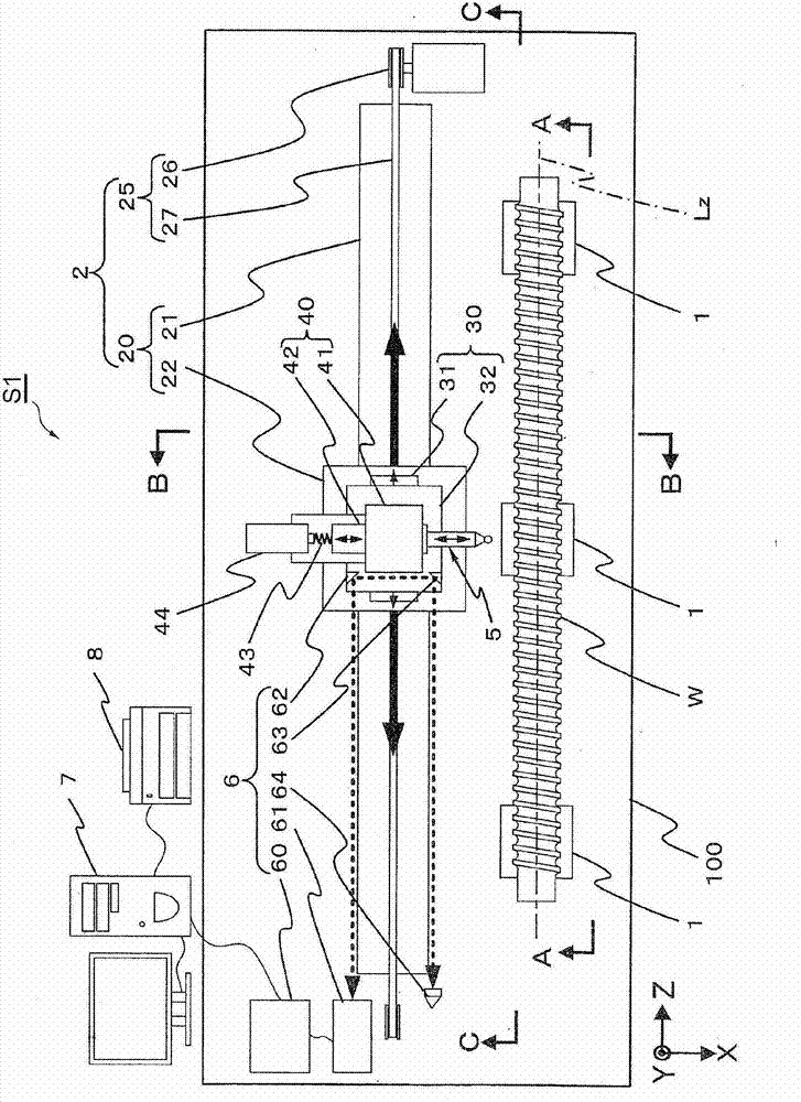
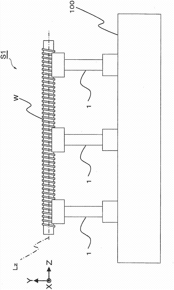
[0026] Hereinafter, a cumulative lead error measuring device for a ball screw shaft and a measuring method using the same according to a first embodiment of the present invention will be described with reference to the drawings. figure 2 It is an explanatory plan view showing the cumulative lead error measuring device of the ball screw shaft according to the first embodiment of the present invention. image 3 is shown from figure 2 An explanatory diagram of the ball screw shaft to be measured and the fixed support base viewed from the A-A arrows. Figure 4 is showing figure 2 An enlarged explanatory diagram of the view from the BB direction of . Figure 5 is showing figure 2 An enlarged explanatory diagram of the view from the direction of C-C. In addition, in Figures 2 to 5 and the following Figure 6 Among them, the X-axis, Y-axis, and Z-axis are orthogonal, and the Z-axis indicates the same direction as the axis center of the measured ball screw shaft, the X-axis...

no. 2 approach )

[0055] Next, a second embodiment of the cumulative lead error measuring device of the ball screw shaft according to the present invention will be described. Figure 6 It is a side explanatory drawing which shows 2nd Embodiment. Since the basic structure and measurement method are the same as those of the first embodiment, description thereof will be omitted.

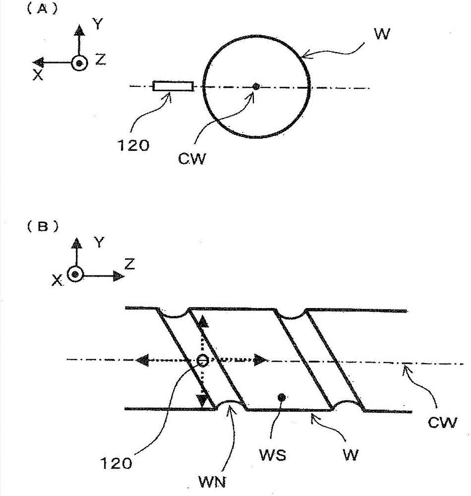
[0056] This embodiment differs from the first embodiment in that in the first embodiment, the ball contact 5 is brought into contact from the X-axis direction perpendicular to the axis Lz of the ball screw shaft W to be measured, but in the second In the embodiment, the ball contact 5 is brought into contact from the Y-axis direction perpendicular to the axis Lz of the ball screw shaft W. As shown in FIG. Therefore, the measurement device S2 of the second embodiment is as Figure 6 The illustrated configuration is such that the ball contact slide mechanism 4 is mounted on the position detection slide mechanism 3 via an...

Embodiment )

[0066] An example of measurement performed by the cumulative lead error measuring device of the ball screw shaft according to the first embodiment will be described below. In a room where the temperature is adjusted to a room temperature of 20°C ± 0.5°C, the ball screw with a shaft diameter of 40mm, a lead pitch of 10mm, and a total length of 1400mm is equivalent to a standard of C3 in JIS (Japanese Industrial Standards) Shaft (manufactured by THK) measures the cumulative lead error of the ball screw shaft.

[0067] First, the ball screw shaft W to be measured is placed statically on three fixed support stands 1 so that the ball screw shaft W to be measured is parallel to the guide shaft 21 of the aerostatic bearing 20 positioning the reciprocating slide mechanism 2 . And the fixed support table 1 is adjusted so that the height of the axis Lz of the ball screw shaft W to be measured coincides with the center height of the ball 50 of the ball contact 5 within ±1 μm. Then, from...


PUM

PropertyMeasurementUnit
Spring constantaaaaaaaaaa

Abstract

The invention relates to a device and a method for determining accumulated lead errors of a ball screw shaft. The device (S1) for determining accumulated lead errors of a ball screw shaft comprises a fixing supporting platform (1) by which the ball screw shaft (W) to be determined is fixed and cannot rotate, a ball contact (5) which abuts against a thread groove of the ball screw shaft to be determined, a ball contact sliding mechanism (4) which enables the ball contact to perform reciprocating motion along the direction orthogonal to a shaft center of the ball screw shaft to be determined and to abuts against the thread groove under the effect of a specified pressing force, a position detection sliding mechanism (3) which enables the ball contact sliding mechanism to perform reciprocating motion horizontally in parallelism with the shaft center, a positioning reciprocating sliding mechanism which enables the position detection sliding mechanism to perform reciprocating motion in the thread part of the ball screw shaft to be determined, and a lead position determining mechanism (6) which detects he position of the ball contact in the direction of the shaft center.

Description

technical field [0001] The present invention relates to a device for measuring the cumulative lead error of a ball screw shaft and a measuring method using the device. Background technique [0002] Conventionally, as a device for measuring the lead error of a ball screw shaft, for example, a measuring device disclosed in Patent Document 1 is known. In this measuring device, a ball of the same size as the ball used for the ball screw shaft to be measured is bonded to the tip of the ball contact, and two ball contacts are centered on the axis of the ball screw shaft to be measured. And it is inserted into the thread groove of the ball screw shaft to be measured at a position staggered by 180 degrees. Then, the measurement pressure is applied in the radial direction of the screw shaft, and the ball screw shaft is rotated while the ball screw shaft to be measured is in contact with the tooth surface on both sides of the thread groove, and the ball is measured by a laser interfe...

Claims


Application Information

Patent Timeline
IPC IPC(8): G01B11/02
CPCF16H25/20G01B5/00G01B5/20G01B11/02G01B21/16G01M13/00
Inventor 高木茂之内村胜次伊藤守
Owner SINTOKOGIO LTD
Why Eureka
Try Eureka