Loading mechanism of mute life testing machine of rolling bearing
A rolling bearing and life test technology, applied in the direction of mechanical bearing testing, etc., can solve the problems of high test cost, unsuitable for rolling bearing manufacturer's manufacturing process diagnosis or product quality evaluation, small load, etc., to achieve uniform load, stable and reliable test load. Effect
- Summary
- Abstract
- Description
- Claims
- Application Information
AI Technical Summary
Problems solved by technology
Method used
Image
Examples
Embodiment 1
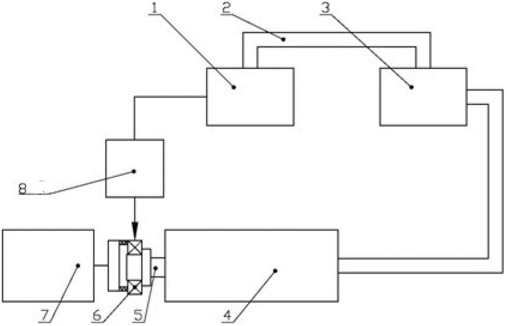
[0029] refer to figure 1 : Rolling bearing silent life testing machine, including the driving mechanism for driving the inner ring of the tested rolling bearing 6 to rotate 4, the loading mechanism connected to the outer ring of the tested rolling bearing 6 for providing test loads 7, and detecting the radial vibration of the tested rolling bearing 6 outer ring The sensor 8 of the signal, the output end of the sensor 8 is connected to the input end of the signal amplification and processing mechanism 1, the output end of the signal amplification and processing mechanism 1 is connected to the input end of the controller 3 through the data control line 2, and the output end of the controller 3 is connected to The feedback input end of the driving mechanism 4 .
[0030] The silent life testing machine for rolling bearings is that the tested rolling bearing 6 is installed under the condition that the radial clearance does not change, and it continues to run under the conditions of...
Embodiment 2
[0054] The difference between the second embodiment and the first embodiment is that the sensor 8 used in the second embodiment is a magnetic induction speed sensor 82 . For its installation diagram, see Figure 7 , the magnetic induction speed sensor 82 is installed on the radial sliding body 42 of the sensor adjustment mechanism, the radial sliding body 42 is connected with the rear end of the axial sliding body 44 through the guide rail, and by adjusting the radial screw mechanism 43 and the axial screw mechanism 45, Make the measuring head of the magnetic induction speed sensor 82 contact with a certain size contact force at the position of 1 / 2 width of the outer diameter of the outer ring of the rolling bearing 6 under test. The contact force of the measuring head of the magnetic induction speed sensor 82 cannot be too small, so as to avoid that when the frequency of the vibration signal is high, the measuring head will be separated from the outer ring of the rolling bear...
PUM
 Abstract
Description
Claims
Application Information
 - R&D
- Intellectual Property
- Life Sciences
- Materials
- Tech Scout
- Unparalleled Data Quality
- Higher Quality Content
- 60% Fewer Hallucinations
Browse by: Latest US Patents, China's latest patents, Technical Efficacy Thesaurus, Application Domain, Technology Topic, Popular Technical Reports.
© 2025 PatSnap. All rights reserved.Legal|Privacy policy|Modern Slavery Act Transparency Statement|Sitemap|About US| Contact US: help@patsnap.com


