
Projection-type capacitive touch panel

A capacitive touch panel, projective technology, applied in the direction of electrical digital data processing, instruments, data processing input/output process, etc., can solve the problems of increasing RC load, reducing ITO utilization rate, affecting panel touch sensitivity, etc. Achieve the effects of reducing impedance, avoiding touch sensitivity drop, and suppressing RC load increase

Inactive Publication Date: 2012-12-05
AU OPTRONICS CORP
View PDF0 Cites 17 Cited by
  • Summary
  • Abstract
  • Description
  • Claims
  • Application Information

AI Technical Summary

Problems solved by technology

However, as the size of the touch panel becomes larger and larger, the above structure will lead to an increase in the RC load, thereby affecting the touch sensitivity of the panel
In addition, designs such as ITO conductive bridges will also reduce the utilization of ITO

Method used


Image

  • Projection-type capacitive touch panel
  • Projection-type capacitive touch panel
  • Projection-type capacitive touch panel

Examples


Embodiment Construction

[0027] In order to make the technical content disclosed in this application more detailed and complete, reference may be made to the drawings and the following various specific embodiments of the present invention, and the same symbols in the drawings represent the same or similar components. However, those skilled in the art should understand that the examples provided below are not intended to limit the scope of the present invention. In addition, the drawings are only for schematic illustration and are not drawn according to their original scale.

[0028] The specific implementation manners of various aspects of the present invention will be further described in detail below with reference to the accompanying drawings.

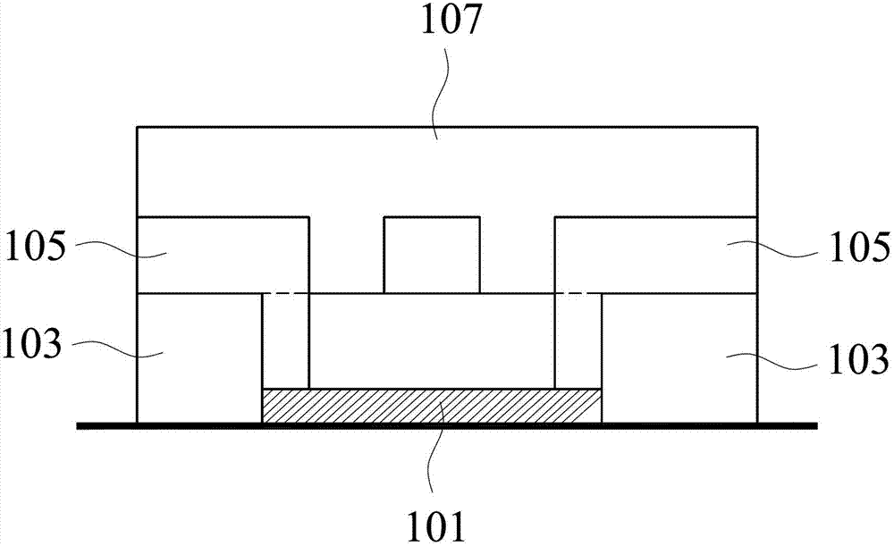
[0029] figure 1 A schematic diagram showing the principle of a projected capacitive touch panel in the prior art electrically connecting sensors on an axis through a conductive bridge.

[0030] refer to figure 1 , the projected capacitive touch panel inc...


PUM


Abstract

The invention provides a projection-type capacitive touch panel, which comprises a transparent substrate, a first conductive layer arranged on a surface of the transparent substrate, a first insulation layer which is provided with a plurality of first through holes, a second conductive layer arranged on the first insulation layer, a second insulation layer which covers the second conductive layer and is provided with a plurality of second through holes, and a third conductive layer, wherein a first sensor of the second conductive layer is electrically coupled to the first conductive layer through the first through holes; a pattern of the first conductive layer or the second conductive layer is the same as and overlapped with a pattern of the third conductive layer; and the third conductive layer is electrically coupled to the first conductive layer and the second conductive layer through the first through holes and the second through holes. By the projection-type capacitive touch panel, the third conductive layer is electrically coupled to the first conductive layer and the second conductive layer through the through holes in the first conductive layer and the second conductive layer; the impedance can be effectively reduced in a manner that a plurality of conductive layers are connected in parallel with one another; the number of resistive and capacitive (RC) loads is prevented from being increased; and a phenomenon that the touch sensitivity of a large-size touch panel is reduced because of the RC loads is avoided.

Description

technical field [0001] The invention relates to a touch panel, in particular to a projected capacitive touch panel. Background technique [0002] The current projected capacitive touch panel generally includes two layers of glass or film stacked up and down, one layer of glass is provided with a plurality of diamond-shaped sensors for detecting the X coordinate in the two-dimensional coordinate system, and the other A layer of glass is also provided with a plurality of diamond-shaped sensors for detecting the Y coordinate in the two-dimensional coordinate system. Each diamond-shaped sensor includes a pair of capacitors, and there is a symbiotic capacitance between each capacitor pair, and an electric field is generated on the surface of the sensor, which is projected to the outside of the screen through non-conductors such as glass or film. When the user directly touches the glass, the control chip will periodically read the state of each ITO electrode in the two-dimensiona...

Claims


Application Information

Patent Timeline
IPC IPC(8): G06F3/044
Inventor 郑尊谦郭俊谷
Owner AU OPTRONICS CORP
Features
  • Generate Ideas
  • Intellectual Property
  • Life Sciences
  • Materials
  • Tech Scout
  • Unparalleled Data Quality
  • Higher Quality Content
  • 60% Fewer Hallucinations
Learn More