Cooling structure of inner rotor motor

An inner rotor motor and cooling structure technology, applied in cooling/ventilation devices, magnetic circuit shape/style/structure, electromechanical devices, etc. The effect of cooling effect is satisfied

Active Publication Date: 2016-04-27
UNITED AUTOMOTIVE ELECTRONICS SYST
View PDF6 Cites 3 Cited by
  • Summary
  • Abstract
  • Description
  • Claims
  • Application Information

AI Technical Summary

Problems solved by technology

Due to the limited space for installing drive motors in new energy vehicles, it is very difficult to build a cooling system including flow channels for the stator and rotor

Method used


Image

  • Cooling structure of inner rotor motor
  • Cooling structure of inner rotor motor
  • Cooling structure of inner rotor motor

Examples


Embodiment 2

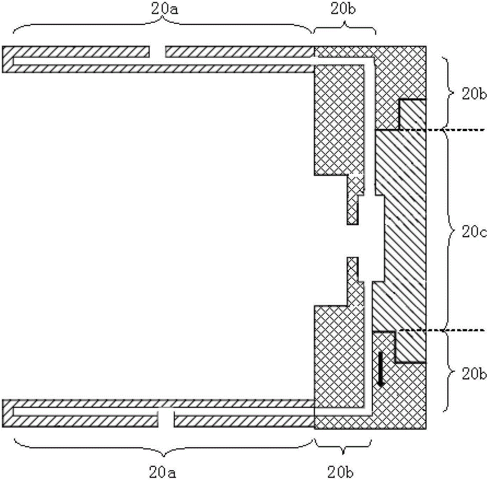
[0053] The shape of the third cavity 20c of the second embodiment can be the same as that of the first embodiment, such as Figure 2d Shown; It can also be only a simple tubular shape, so as to be connected with the second cavity 20b.

[0054] In the above two embodiments, the separation design of the cover 13 and the front cover 9 is mainly for the convenience of assembling the heat conducting rod 11 . Alternatively, the cover 13 and the front end cover 9 can also be integrated, and at this time the second cavity and the third cavity are both in the integrated front end cover.

[0055] The technical advantages of the cooling structure of the inner rotor motor described in the above two embodiments are:

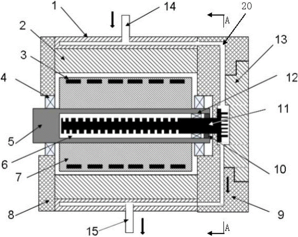
[0056] 1. Avoid the hidden danger of short circuit inside the motor. This is because the heat conduction chamber 6 is filled with non-conductive heat conduction oil, even if the dynamic seal between the rotor shaft 5 and the heat conduction rod 11 fails slightly, a small am...


PUM


Abstract

The present application discloses a cooling structure of an inner rotor motor. The inner rotor motor includes a rotor shaft, a rotor part, a stator part, a front end cover and a cover; the cooling structure includes a third space between the front end cover and the cover. The third cavity is used as a part of the cooling medium channel; there is a heat conduction cavity in the rotor shaft, and its opening is set on the side of the rotor shaft located at the front end cover, and there is a heat conduction medium inside; the first end of the heat conduction rod is located in the heat conduction cavity And in contact with the heat-conducting medium, the second end is located in the third cavity in contact with the cooling medium, the second end and the front end cover are sealed by a static seal; the rotor shaft and the heat-conducting rod are sealed by a dynamic seal; The heat of the rotor part and the rotor shaft is transferred to the second end of the heat conducting rod through the first end of the heat conducting rod in the heat conducting cavity, and dissipated through the cooling medium in the third cavity. The present application satisfies the strict requirements of insulation, sealing and volume while obtaining a good heat dissipation effect of the stator and the rotor.

Description

technical field [0001] The present application relates to an inner rotor electric machine. Background technique [0002] According to the relative position between the stator and the rotor, the motor can be divided into two types: inner rotor and outer rotor. The rotor of an inner rotor motor is surrounded by the stator, ie the rotor is inside. The rotor of the outer rotor motor surrounds the stator, that is, the rotor is outside. [0003] At present, the permanent magnet synchronous motor with inner rotor is usually used as the driving motor in new energy vehicles. Due to the limitation of space and the pursuit of high performance, the heating of the stator and rotor of this inner rotor permanent magnet synchronous motor has become a must. question. [0004] In the existing stator cooling structure of the inner rotor motor, a cooling jacket is fixed on the periphery of the stator core in the form of interference fit or transition fit. The cooling jacket is usually made ...

Claims


Application Information

Patent Timeline
Patent Type & Authority Patents(China)
IPC IPC(8): H02K9/19H02K1/32H02K9/22
CPCH02K1/32H02K9/227H02K9/225H02K5/203H02K9/197
Inventor 屈晨竹陈思远
Owner UNITED AUTOMOTIVE ELECTRONICS SYST
Why Eureka
Try Eureka