Control unit and driving apparatus using the same

A technology of control unit and drive device, applied in the direction of connection with control/drive circuit, control system, electromechanical device, etc., can solve problems such as adverse effects

Inactive Publication Date: 2012-12-05
DENSO CORP
View PDF5 Cites 19 Cited by
  • Summary
  • Abstract
  • Description
  • Claims
  • Application Information

AI Technical Summary

Problems solved by technology

[0004] In the prior art described above, the magnetic field generated by the current flowing through the switching device can adversely affect other electronic parts and / or components such as connectors

Method used


Image

  • Control unit and driving apparatus using the same
  • Control unit and driving apparatus using the same
  • Control unit and driving apparatus using the same

Examples


no. 1 approach )

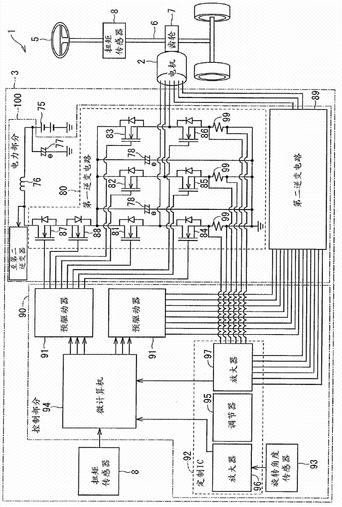
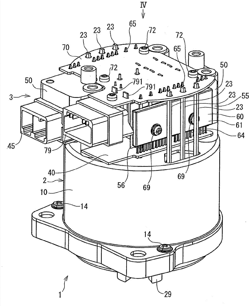
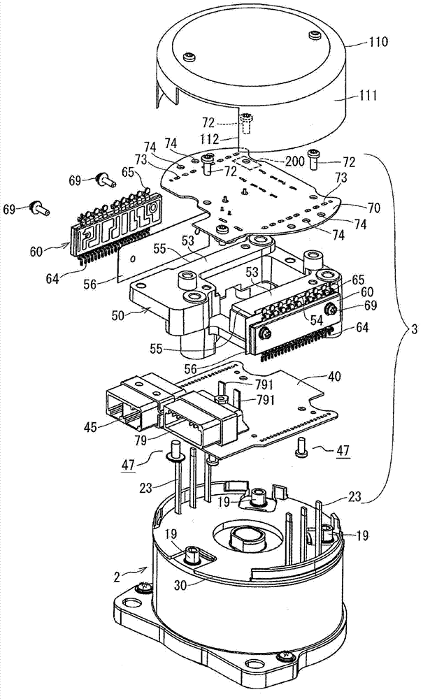
[0020] Will refer to Figure 1 to Figure 7 The drive device 1 of the first embodiment of the present disclosure will be described. The drive device 1 is applied to an electric power steering system (EPS) for a vehicle. The driving device 1 is composed of a motor 2 and a control unit 3.

[0021] Will refer to figure 1 Explain the electrical structure of EPS.

[0022] Such as figure 1 As shown, the driving device 1 generates rotational torque on the steering column shaft 6 via the gears of the gear box 7 provided in the steering column shaft 6 to assist the steering operation of the steering wheel 5, wherein the steering column shaft 6 is a steering wheel 5 for a vehicle Axis of rotation. More specifically, when the vehicle driver operates the steering wheel 5, the torque sensor 8 detects the steering torque generated in the steering column shaft 6, and obtains the vehicle speed information from the controller area network (CAN, not shown) to assist the vehicle driving The steerin...

no. 2 approach )

[0090] Will refer to Figure 8 The driving device according to the second embodiment of the present disclosure is explained.

[0091] Such as Figure 8 As shown, an inclined surface 57 and a vertical surface 58 are formed on the radially inner surface of each heat receiving portion 55 of the heat sink 50. The inclined surface 57 is inclined with respect to the rotation axis O of the motor 2 and corresponds to the parallel surface 54 in the first embodiment. The vertical surface 58 is arranged in parallel with the rotation axis O of the motor 2. The respective power modules 60 are arranged on the inclined surface 57 so as to be parallel to the inclined surface 57. The power terminal 65 is arranged in parallel with the vertical surface 58.

[0092] The second embodiment has the same advantages as the first embodiment.

[0093] (Further modification)

[0094] In the above-described embodiment, the power terminal 65 (connection part) and the power output terminal 23 (stator coil termin...


PUM


Abstract

The invention relates to a control unit for controlling an electric load comprising: power-input terminals (791), power-output terminals (23), multiple switching devices (81-86), wiring portions (65) and a metal chassis (50), wherein the wiring portions (65) of power modules (60) are magnetically coupled to the power-output terminals (23) and the power-input terminals (791), the metal chassis (50) has a parallel plane (54) in parallel to the power modules (60) and the wiring portions (65), and a magnetic field generated by electric current flowing through the switching devices (81-86) and the wiring portions (65) is canceled by a magnetic field generated by eddy current flowing in the metal chassis (50). The invention further relates to a driving apparatus using the aforementioned control unit.

Description

Technical field [0001] The invention relates to a control unit and a driving device that uses the control unit to drive and control the operation of a motor. Background technique [0002] According to a three-phase motor known in the prior art, this motor is driven to rotate when three-phase alternating current is supplied to the motor. [0003] In the case where the power supply for the three-phase motor is a DC power supply with a predetermined voltage, it is necessary to provide a control unit with a plurality of switching devices, and switch the current supplied to the stator coil according to the control unit so that the stator coil currents of different phases Is provided to the corresponding stator coil (for example, a three-phase coil). For example, as disclosed in Japanese Patent Publication No. H03-89837, the switch device is arranged on the heat sink. [0004] In the aforementioned prior art, the magnetic field generated by the current flowing through the switching devic...

Claims


Application Information

Patent Timeline
Patent Type & Authority Applications(China)
IPC IPC(8): H02P25/16
CPCH02K3/50H02K3/505H02K2203/03H02K11/0073H02K11/33
Inventor 增泽高志山崎雅志泷浩志
Owner DENSO CORP
Why Eureka
Try Eureka