
LED lamp and control circuit thereof

A technology of LED lamps and control circuits, which is applied in the layout of electric lamp circuits, electric light sources, lighting devices, etc., can solve the problems of insufficient brightness and automatic dimming.

Inactive Publication Date: 2012-12-05
OCEANS KING LIGHTING SCI&TECH CO LTD +1
View PDF7 Cites 10 Cited by
  • Summary
  • Abstract
  • Description
  • Claims
  • Application Information

AI Technical Summary

Problems solved by technology

[0003] The technical problem to be solved by the present invention is to provide a control circuit for LED lamps, which can automatically adjust the brightness of the above-mentioned LED lamps according to the change of the ambient brightness. Dimming

Method used


Image

  • LED lamp and control circuit thereof
  • LED lamp and control circuit thereof
  • LED lamp and control circuit thereof

Examples


Embodiment Construction

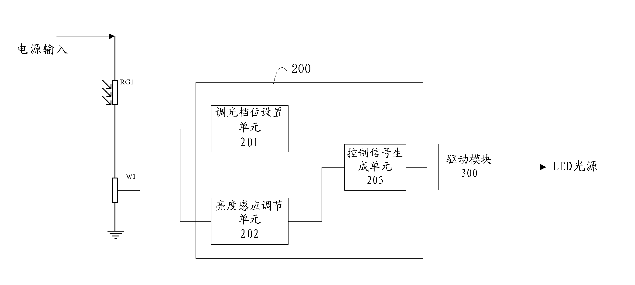
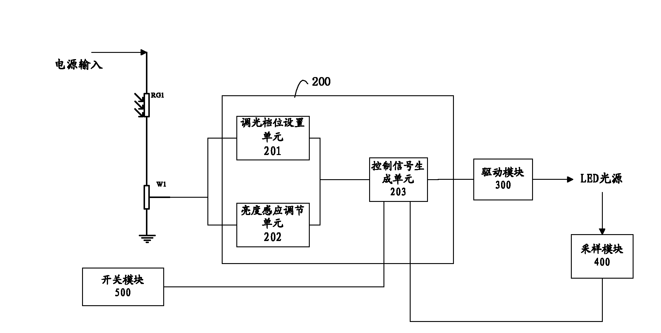
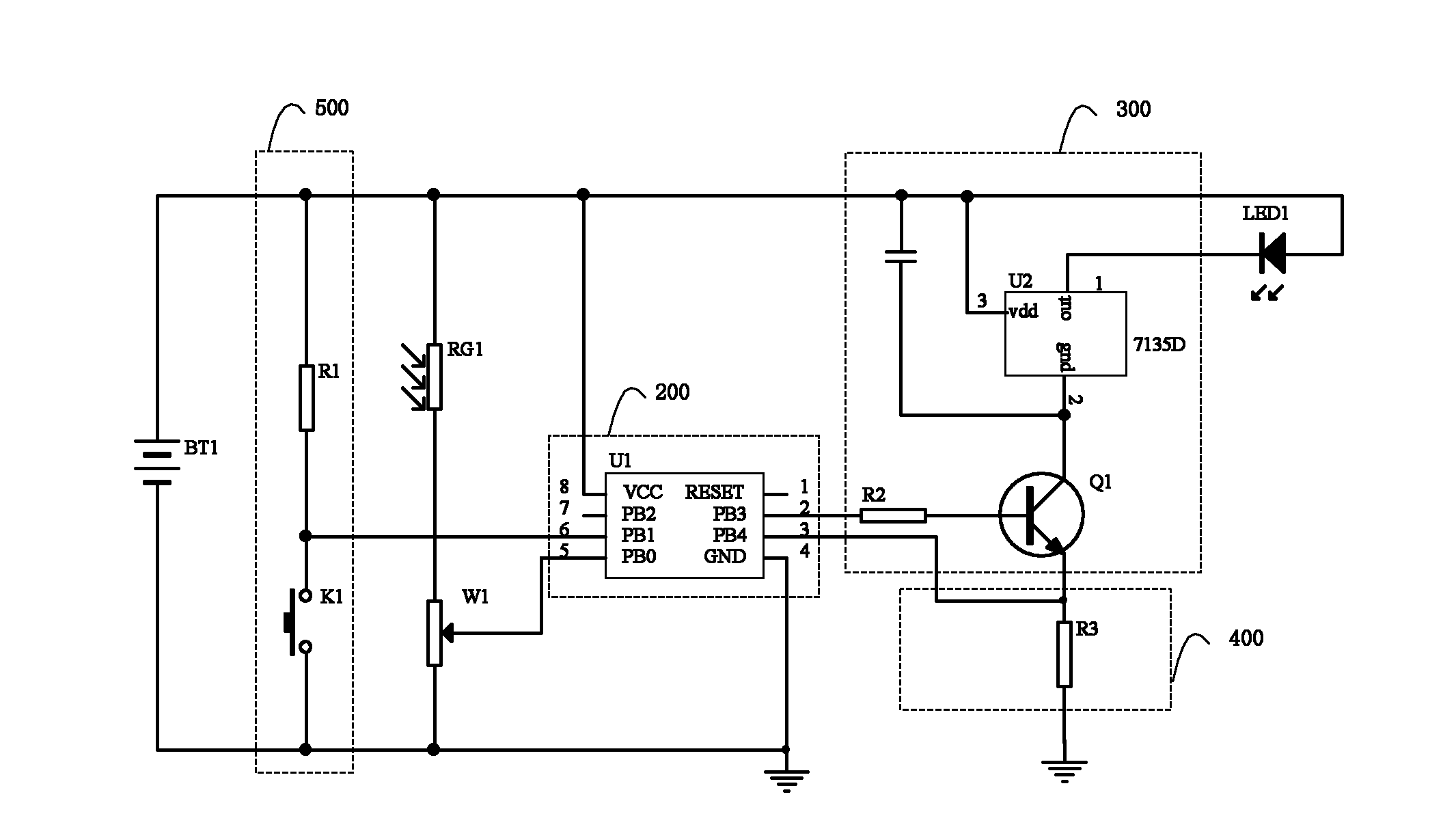
[0026] Such as figure 1 As shown, in the logic structure diagram of Embodiment 1 of the control circuit of the LED lamp of the present invention, the control circuit of the LED lamp includes:

[0027] The photoresistor RG1 and the dimming potentiometer W1 are connected in series between the power supply input and the ground terminal, and the adjustable terminal of the dimming potentiometer W1 is connected to the first input terminal of the control module 200;

[0028] A control module 200 for processing and analyzing the voltage signal received by the first input terminal;

[0029] The driving module 300 connected to the LED light source is used to drive the LED light source to emit light of corresponding brightness according to the PWM modulation wave output by the control module 200;

[0030] The control module 200 includes a dimming gear setting unit 201, a brightness sensing adjustment unit 202, and a control signal generating unit 203. The dimming gear setting unit 201 r...


PUM


Abstract

The invention discloses an LED lamp and a control circuit thereof. The control circuit comprises a photosensitive resistor, a light adjusting potentiometer and a control module, wherein the photosensitive resistor and the light adjusting potentiometer are connected in series between a power supply input end and a grounding end; the adjustable end of the light adjusting potentiometer is connected with the first input end of the control module; the control module is used for processing and analyzing a voltage signal received by the first input end and driving an LED light source to emit light with corresponding luminance; in the control module, a light adjusting gear setting unit receives a first voltage signal input by the first input end due to the change of the light adjusting potentiometer, and chooses the corresponding duty ratio of a PWM modulation wave; a luminance sensing adjusting unit receives a second voltage signal input by the first input end due to the change of the photosensitive resistor, and chooses the corresponding duty ratio of the PWM modulation wave; and a control signal generating unit generates the PWM modulation wave according to the duty ratio chosen by the light adjusting gear setting unit or the luminance sensing adjusting unit. According to the technical scheme provided by the embodiment of the invention, the LED lamp can automatically adjust the light with the change of the environment luminance.

Description

technical field [0001] The invention relates to LED lighting technology, in particular to an LED lamp and a control circuit thereof. Background technique [0002] With the continuous development of science and technology, new products and new technologies continue to innovate. As a new type of light source, LED has the characteristics of energy saving, environmental protection, and high efficiency. The technology has matured and is used in various fields. LED is widely used as a light source. However, the existing LED lamps can only maintain a constant brightness output set by the user, and cannot automatically adjust the brightness according to the change of the ambient brightness, which is not conducive to energy saving and environmental protection, and it is uncomfortable for users to use. Contents of the invention [0003] The technical problem to be solved by the present invention is to provide a control circuit for LED lamps, which can automatically adjust the bright...

Claims


Application Information

Patent Timeline
IPC IPC(8): H05B37/02
Inventor 周明杰黄柯青
Owner OCEANS KING LIGHTING SCI&TECH CO LTD
Learn More