Conveying device for conveying isolated long workpieces

A technology for conveying devices, workpieces, applied in the direction of conveyors, transport and packaging, needles

Inactive Publication Date: 2016-03-02
WAFIOS AKTIENGES
View PDF8 Cites 0 Cited by
  • Summary
  • Abstract
  • Description
  • Claims
  • Application Information

AI Technical Summary

Problems solved by technology

On the other hand, however, if workpieces with larger or smaller diameters are conveyed, the same problem arises here again

Method used


Image

  • Conveying device for conveying isolated long workpieces
  • Conveying device for conveying isolated long workpieces
  • Conveying device for conveying isolated long workpieces

Examples


Embodiment Construction

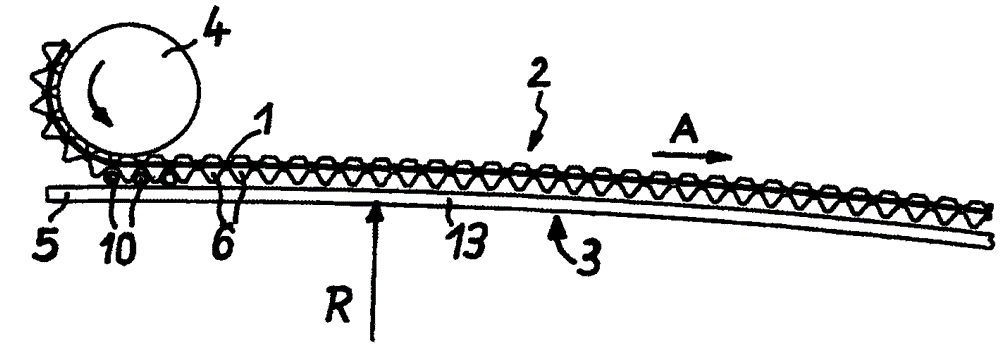
[0025] figure 1 A partial conveying device for elongated workpieces such as nail blanks, tubes, bolts, pins or the like is shown in substantially great detail, wherein the device has a continuous toothed belt 1 and a relatively long track 2 running almost straight, The conveying function is performed along this track.

[0026] Coordinated with this track 2 in the direction of the toothed belt 1 (curve radius R) is the guide rail 3 which runs over its extension and bends, albeit only at a small angle.

[0027] The toothed belt 1 is guided to the figure 1 Around the center left-hand side wheel 4 to drive its components intermittently, where in figure 1 The only defined curvature of the toothed belt 1 around the deflection wheel 4 is shown in the schematic diagram of FIG.

[0028] On this side, the end region 5 extends the guide rail 3 somewhat beyond the position of the deflection wheel 4 .

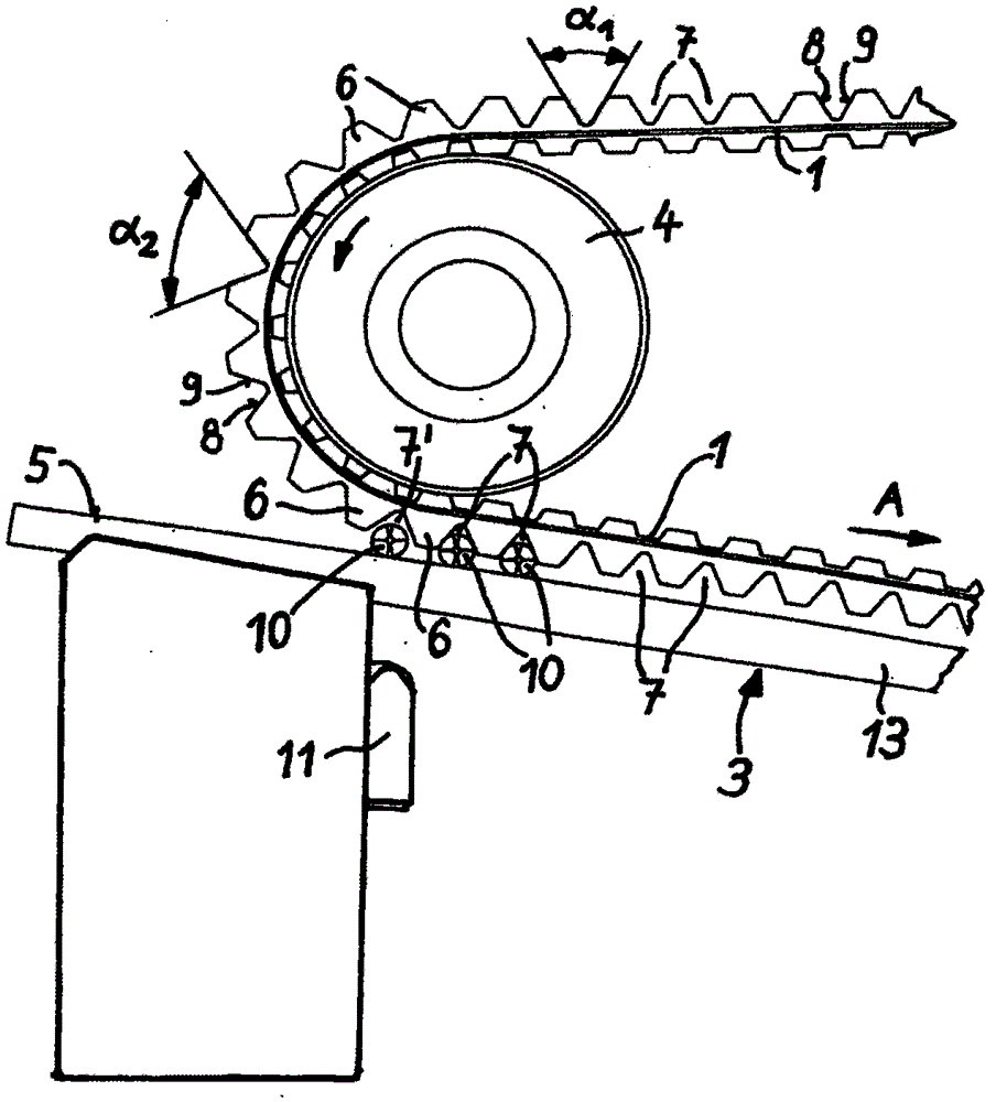
[0029] now refer to figure 2 , to display figure 1 The enlarged part, that is, t...


PUM


Abstract

A conveying device for elongated workpieces (10), transverse to its longitudinal direction, comprising: a continuously driven toothed belt (1) which travels over an inflection point (4) and which The toothed belt (1) has grooves (7, 7'), each groove accommodates a work piece (10), and the conveying means comprises a feed point at which the work piece (10) is introduced into the groove (7' ), the workpiece protrudes through its outer surface over the groove (7'), and slides against the guide rail (3), which coordinates with the toothed belt (1) and at the two inflection points (4), and the guide rail has a protruding profile towards the toothed belt (1), each groove (7) is formed with a cross-section between two die teeth (6) protruding from the toothed belt (1) , so that the inserted workpiece (10) abuts only on the two sides (8, 9) of the die tooth (6) incorporating the groove (7). The toothed belt (1) rotating at the point of inflection (4) thus expanding the groove (7') engages the feed point so that the workpiece (10) is axially drawn from the longitudinal side (13) of the toothed belt (1) Push into the expanded groove (7') without abutting against the sides (8, 9) of the die tooth (6) incorporating the groove (7').

Description

technical field [0001] The invention relates to a conveying device for conveying isolated elongated workpieces, such as wires, transversely to its longitudinal direction. The conveying device has a continuously driven toothed belt which travels over at least two inflection points and which has grooves on its exterior facing the workpieces, each groove receiving a workpiece, and the conveying device having a feed point, in each case, when the workpiece is introduced into the groove at this feed point, the workpiece projects radially beyond said groove by its outer surface area and rests in a sliding manner on the guide rail , the guide rail is coordinated with the toothed belt and runs at a distance from said belt and in the region between two inflection points, and the guide rail has a curved profile in the toothed belt towards the groove. Background technique [0002] Such conveying devices are used, for example, to convey nail blanks in nail production machines. [0003]...

Claims


Application Information

Patent Timeline
Patent Type & Authority Patents(China)
IPC IPC(8): B21G1/12B65G15/14B65G19/02
CPCB21F23/005B21G1/12B65G19/02B65G2201/0217B65G15/14
Inventor 维尔纳·戈德特尼尔
Owner WAFIOS AKTIENGES
Why Eureka
Try Eureka