
Novel coating device and coating method

A coating device and coating technology, which are applied to the coating, the device for coating liquid on the surface, etc., can solve the problems of sparse spray holes, high temperature of the box 401, blockage of the spray holes, etc., and reduce labor intensity. , Improve production efficiency and reduce consumption

Active Publication Date: 2014-12-10
JIANGSU CHUANGYI PRECISION FORGING
View PDF6 Cites 0 Cited by
  • Summary
  • Abstract
  • Description
  • Claims
  • Application Information

AI Technical Summary

Problems solved by technology

[0005] (1) In order to ensure the injection pressure, the injection holes of the spray ring 403 are set small, so the injection holes are small and easy to block, and need to be disassembled and cleaned every day, which brings inconvenience to the operator;
[0006] (2) The width of the spray ring 403 is limited, and the spray holes are sparsely arranged. If the workpiece (bar material) 406 passes through fast, or some spray holes are blocked, the coating material will adhere unevenly to the workpiece (bar material) 406 Or partly without adhesion, affecting the lubrication effect of warm forging;
[0007] (3) The air pressure required when injecting graphite is relatively large, and the diaphragm pump that provides the air pressure is easily damaged;
[0008] (4) The front and rear of the cabinet 401 are intermediate frequency heating furnaces, resulting in high internal temperature of the cabinet 401, and the coating material sprayed from the spray ring 403 is in the form of mist, which is easy to evaporate, and will dry on the inner wall of the cabinet 401, resulting in waste , which is not conducive to the recycling of coating materials

Method used


Image

  • Novel coating device and coating method
  • Novel coating device and coating method
  • Novel coating device and coating method

Examples


Embodiment Construction

[0036] The present invention will be described in further detail below in conjunction with the accompanying drawings.

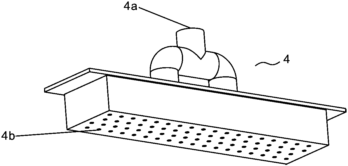
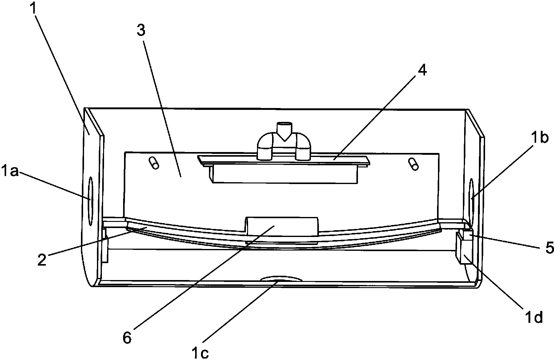
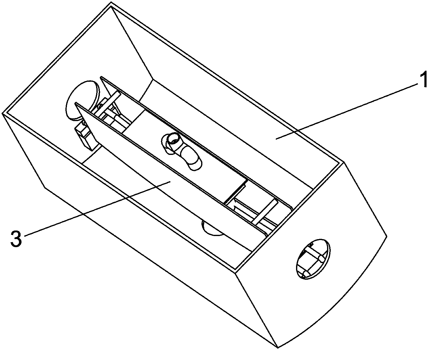
[0037] Such as Figure 1 ~ Figure 3 As shown in the figure, box body 1, workpiece inlet 1a, workpiece outlet 1b, pipe interface 1c, rack pin socket 1d, rack rail 2, dip tank 3, storage box 4, coating material inlet 4a, spray Hole 4b, shelf pin 5, workpiece 6.

[0038] Embodiments of the present invention are described in detail below, examples of which are shown in the drawings, wherein the same or similar reference numerals designate the same or similar elements or elements having the same or similar functions throughout. The embodiments described below by referring to the figures are exemplary only for explaining the present invention and should not be construed as limiting the present invention.

[0039] In the description of the present invention, the terms "inner", "outer", "upper", "lower", "front", "rear", "bottom", "top" and the like indicate that t...


PUM


Abstract

The invention discloses a novel coating device and a coating method. The coating device comprises a box body, a material rack rail, a storage box and an impregnating groove, wherein a workpiece inlet is molded at one end of the box body, and a workpiece outlet is molded at the other end of the box body; the material rack rail extends to the workpiece outlet from the workpiece inlet; the storage box is positioned on the upper part of the material rack rail; a coating material inlet is formed on the storage box body; a spraying hole is formed at the bottom of the box body; the bottom of the impregnating groove has a recessed shape; and the material rack rail penetrates through the impregnating groove. The coating effect is obviously improved, the coating is uniform, the production efficiency is improved, the labor intensity is lightened, the coating materials are effectively recycled, and the coating material consumption is reduced.

Description

technical field [0001] The invention relates to a coating device and a coating method using the device, in particular to a dipping coating device and a coating method for coating a workpiece. Background technique [0002] Coating is a solid continuous film obtained by one application of paint. It is a thin plastic layer coated on metal, fabric, plastic and other substrates for the purpose of protection, insulation and decoration. Protective, pigmented coatings are applied to surfaces by various coating techniques. The more common technique used in commercial operations is the spray coating method. The spray coating method includes the following steps: spraying the article to be coated, and then either recovering the coated article from the residual liquid, or directly separating the workpiece from the residual liquid through a movable conveying device. This treatment is especially suitable for commercial operations where complete and rapid coating of workpieces is required...

Claims


Application Information

Patent Timeline
Patent Type & Authority Patents(China)
IPC IPC(8): B05C9/02B05C11/10B05C13/00
Inventor 夏勇吴玉平
Owner JIANGSU CHUANGYI PRECISION FORGING
Learn More