
Transmission shaft balancing device of rolling machine

A technology of balancing device and transmission shaft, which is applied to the driving device of metal rolling mill, metal rolling, metal rolling, etc. Effect

Inactive Publication Date: 2012-12-12
江苏中重智能装备科技有限公司
View PDF7 Cites 2 Cited by
  • Summary
  • Abstract
  • Description
  • Claims
  • Application Information

AI Technical Summary

Problems solved by technology

[0003] Aiming at the shortcomings of the poor balance of the transmission shaft in the above-mentioned existing production technology, the applicant provides a rolling mill transmission shaft balancing device with reasonable structure and convenient operation, so that the transmission shaft can always maintain balance during disassembly and installation, and its stability good, high reliability

Method used


Image

  • Transmission shaft balancing device of rolling machine
  • Transmission shaft balancing device of rolling machine
  • Transmission shaft balancing device of rolling machine

Examples


Embodiment Construction

[0025] The specific implementation manner of the present invention will be described below in conjunction with the accompanying drawings.

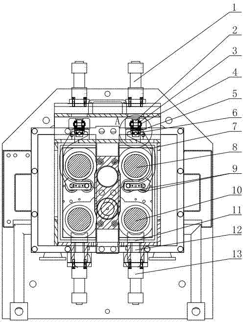
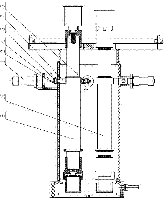
[0026] Such as figure 1 and figure 2 As shown, the rolling mill transmission shaft balancing device of this embodiment includes an upper transmission shaft 8 and a lower transmission shaft 10 installed in the frame, the two ends of the upper transmission shaft 8 and the lower transmission shaft 10 are respectively supported by bearing devices, and the upper transmission shaft A first balance device is installed at the fulcrum of 8, and a second balance device is installed at the fulcrum of the lower transmission shaft 10;

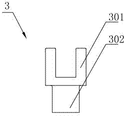
[0027] The structure of the first balance device is as follows: it includes the first oil cylinder 1 installed on the upper part of the upper transmission shaft 8, and also includes the lifting ring 7 cooperating with the upper transmission shaft 8, and the head of the lifting ring 7 is connected to the first oil cyli...


PUM


Abstract

The invention relates to a transmission shaft balancing device of a rolling machine. The transmission shaft balancing device comprises an upper transmission shaft and a lower transmission shaft which are installed in a frame. Two ends of the upper transmission shaft and the lower transmission shaft are respectively supported by a bearing device, a first balancing device is installed at the pivot position of the upper transmission shaft, and a second balancing device is installed at the pivot position of the lower transmission shaft. The transmission shaft balancing device is reasonable in structure and convenient to operate, effectively controls and maintains balance of the upper transmission shaft in assembly and disassembly by controlling stretching and retreating of a first piston rod of a first oil cylinder and effectively controls and maintains balance of the upper transmission shaft in assembly and disassembly by controlling stretching and retreating of a second piston rod of a second oil cylinder. Disassembly of the transmission shaft is not affected by length and weight of the shaft, and the transmission shaft is convenient and quick to operate and remarkably improves production efficiency.

Description

technical field [0001] The invention relates to an auxiliary device of rolling mill equipment, in particular to a balancing device of a rolling mill transmission shaft. Background technique [0002] In metallurgical production, when the rolling mill equipment is working, whether it is cold rolling or hot rolling, the roll system is composed of backup rolls, intermediate rolls, and work rolls, which are important components of the rolling mill equipment. The work rolls, intermediate rolls in the roll system Rollers and back-up rolls are always subject to rolling forces that change in direction and size. The roller usually transmits power and support through the transmission shaft. The shaft length of the transmission shaft is long, has a certain degree of winding, and the balance is poor. When the roller is required to be used for a long time, fatigue wear or damage will occur, and the roller needs to be maintained or replaced. Therefore, due to the poor balance of the trans...

Claims


Application Information

Patent Timeline
Patent Type & Authority Applications(China)
IPC IPC(8): B21B35/14
Inventor 唐明胡智伟张靖徐强琦唐国震
Owner 江苏中重智能装备科技有限公司
Learn More