Stamping mould drawing mechanism

A technology of stamping dies and pressing plates, which is applied in the field of multi-station metal molds, can solve problems such as long up and down movement strokes, rapid processing of difficult dies, and failure of drawing materials, and achieves the advantages of facilitating high-speed operations, improving production efficiency, and fast operations Effect

Inactive Publication Date: 2012-12-12
BOXIANG ULTRA PRECISION TOOLING TECH KUNSHAN
View PDF5 Cites 5 Cited by
  • Summary
  • Abstract
  • Description
  • Claims
  • Application Information

AI Technical Summary

Problems solved by technology

[0002] In the continuous metal stamping die, it is necessary to realize the synchronous conveying of the material belt and the mold through the pulling mechanism. The pulling block of the common pulling mechanism is elastically floating verticall

Method used


Image

  • Stamping mould drawing mechanism
  • Stamping mould drawing mechanism

Examples


Embodiment

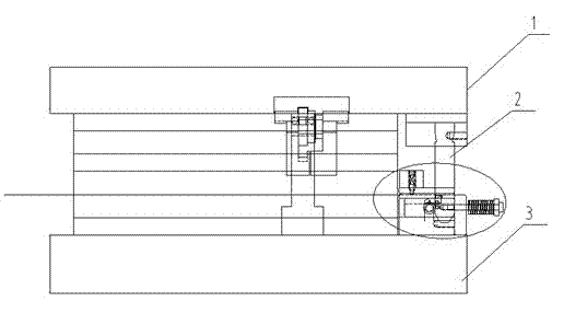
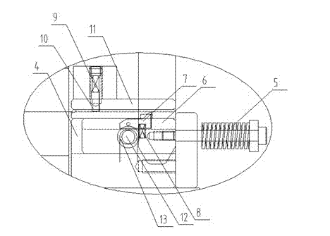
[0013] Embodiment: A material pulling mechanism for a stamping die, comprising an insertion knife 2 fixed on an upper die 1, a concave pulling groove 4 located on a lower die 3, a pulling elastic member 5, a pulling slider 6, a pulling Material block 7, material pulling floating elastic part 8, anti-retraction elastic part 9, anti-retraction block 10 and pressure plate 11, the insertion knife 2 is fixed below the upper die 1, and the material pulling slider 6 can move along the material belt The linear sliding in the conveying direction is located in the pulling groove 4 of the lower die 3. The two ends of the pulling elastic member 5 are fixedly connected with the lower die 3 and the pulling slider 6 respectively. The lower end of the inserting knife 2 is inclined. It can extend into the pulling groove 4 and push the pulling slider 6 to move in reverse along the belt conveying direction. One end of the pulling block 7 along the feeding direction of the material belt is hinged ...


PUM


Abstract

The invention discloses a stamping mould drawing mechanism; a drawing slider can be slidably arranged in the drawing groove of a lower mould; both ends of an elastic drawing piece are fixedly connected with the lower mould and the drawing slider; the lower end of a slotting tool below an upper mould can extend into the drawing groove and pushes the drawing slider to reversely move along the conveying direction of a material belt; one end of the drawing block is hinged onto the drawing slider, and the other end of the drawing block is provided with a first barb structure; one side of the first barb structure which is back to the conveying direction of the material belt is an oblique surface; an upper end of a drawing floating elastic piece which is positioned in the drawing slider is tightly abutted to the lower part of the other end of the drawing block; a pressure plate is fixedly connected with the lower mould and is arranged above the material belt; the lower end of an anti-retraction stop god which can longitudinally slide in the pressure plate slidably is provided with a second barb structure; one side of the second barb structure which is back to the conveying direction of the material belt is also an oblique surface; an anti-retraction elastic piece is positioned in the pressure plate and is connected with the anti-retraction stop dog; and according to the stamping mould drawing mechanism, quick operation can be realized, the high-speed operation of the stamping mould is conveniently realized, and the production efficiency is improved.

Description

technical field [0001] The invention relates to a multi-station hardware mold, in particular to a material pulling mechanism for a stamping mold. Background technique [0002] In the continuous metal stamping die, it is necessary to realize the synchronous conveying of the material belt and the mold through the pulling mechanism. The pulling block of the common pulling mechanism is elastically floating vertically and vertically through the spring, and its up and down movement stroke is long and the reaction speed is slow. To achieve rapid mold processing, the spring is prone to aging and loss of elasticity, resulting in failure of the pulling material. Contents of the invention [0003] In order to overcome the above defects, the present invention provides a stamping die pulling mechanism, the stamping die pulling mechanism has a simple structure, fast pulling speed, fast response, can realize high-speed operation of the stamping die, and improve stamping efficiency. [0...

Claims


Application Information

Patent Timeline
IPC IPC(8): B21D37/10
Inventor 刘健
Owner BOXIANG ULTRA PRECISION TOOLING TECH KUNSHAN
Why Eureka
Try Eureka