Mold base device

A technology of bottom plate and staggered arrangement, applied in ceramic molding machines, manufacturing tools, etc., can solve the problems of uneven density, low carbon block density, and carbon block discharge damage, etc., to achieve uniform density, improve pass rate, and high density. Effect

Inactive Publication Date:
View PDF6 Cites 1 Cited by
  • Summary
  • Abstract
  • Description
  • Claims
  • Application Information

AI Technical Summary

Problems solved by technology

[0002] When the anode or cathode carbon block is produced by a vibration forming machine, the density of the carbon block will be low or uneven because the mold cover, mold base and vibration table are sometimes not on the same center line.
The mold base on the vibrating table has no heating system, and the mold base is preheated by the temperature of the paste. Since the temperature of the mold base is always less than or equal to the temperature of the paste, during a period of early production, the lower part of the anode or cathode carbon block Not smooth, often damaged when the carbon block is discharged, affecting the quality of the product

Method used


Image

  • Mold base device
  • Mold base device

Examples


Embodiment Construction

[0013] The embodiments of the present invention will be described in detail below in conjunction with the accompanying drawings, but the protection scope of the present invention is not limited by the embodiments.

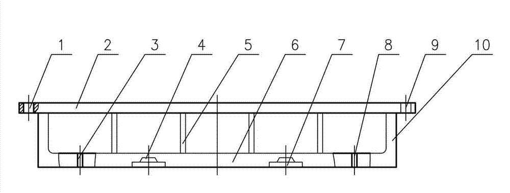
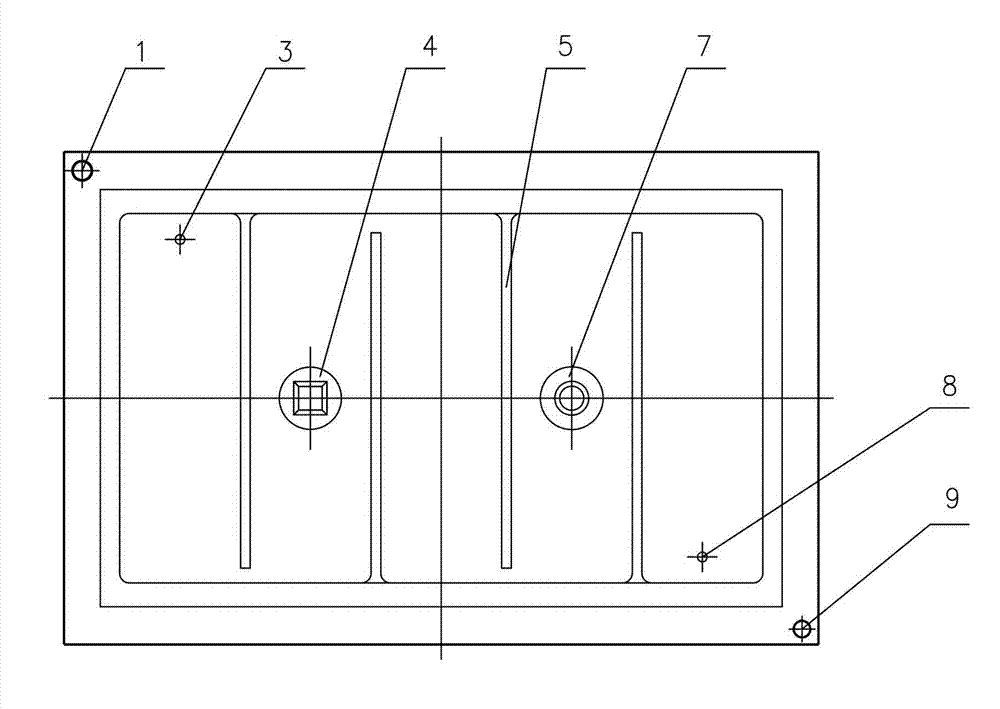
[0014] Such as figure 1 and figure 2 The structure of the mold base device shown is as follows: the upper cover plate 2, the side wall 10 and the bottom plate 6 form a hollow cavity, and the interior of the hollow cavity is divided into multiple heating chambers by partitions 5, and the adjacent partitions 5 are staggered. Arranged to facilitate heat circulation, the top of the partition 5 is connected to the inner side of the upper cover 2 , the bottom of the partition 5 is connected to the inner side of the bottom plate 6 , and the two ends of the bottom plate 6 are connected to the side wall 10 . Both sides of the bottom plate 6 are respectively provided with a heat source inlet 3 and a heat source outlet 8, and the lower part of the bottom plate 6 is also pro...


PUM


Abstract

The invention relates to a mold base device. The mold base device is structurally characterized in that a hollow cavity consists of an upper cover plate, side walls and a bottom plate, the inside of the hollow cavity is divided into a plurality of heating cavities by partition plates, the adjacent partition plates are staggered with one another, tops of the partition plates are connected with the inner side of the upper cover plate, bottoms of the partition plates are connected with the inner side of the bottom plate, two ends of the bottom plate are connected with the side walls, a heat source inlet and a heat source outlet are respectively arranged on two sides of the bottom plate, a second positioning hole and a third positioning hole are further arranged on the lower portion of the bottom plate and are not communicated with the hollow cavity, and a first positioning hole and a fourth positioning hole are arranged on the upper cover plate. The mold base device has the advantages that a mold sleeve, a mold base and a vibrating platform can be positioned on the same center line, and excitation force generated by the vibrating platform can effectively act on paste materials, so that produced anode or cathode carbon blocks are high and uniform in density; and bottom surfaces of the carbon blocks are smooth, and qualified rate of the products is increased.

Description

technical field [0001] The invention relates to a mold base device, in particular to a mold base device for producing anode or cathode carbon blocks by a vibration forming method. Background technique [0002] When the anode or cathode carbon block is produced by a vibration forming machine, the density of the carbon block will be low or uneven because the mold cover, mold base and vibration table are sometimes not on the same center line. The mold base on the vibrating table has no heating system, and the mold base is preheated by the temperature of the paste. Since the temperature of the mold base is always less than or equal to the temperature of the paste, during a period of early production, the lower part of the anode or cathode carbon block It is not smooth, and it is often damaged when the carbon block is discharged, which affects the quality of the product. Contents of the invention [0003] The present invention provides a mold base device for producing anode o...

Claims


Application Information

Patent Timeline
Patent Type & Authority Applications(China)
IPC IPC(8): B28B7/24B28B1/08
Inventor 齐忠昱方明勋王林华王书宝卢延峰
Why Eureka
Try Eureka