A foam tube extrusion die with adjustable feed flow rate

A technology of feed flow and extrusion mold, which is applied in the field of molds for manufacturing plastic pipes, can solve the problems of invariable position and poor controllability of slurry flow, and achieve the effects of ensuring stability, facilitating flexible control, and ensuring sealing

Active Publication Date: 2015-08-05
昆山圣源机械有限公司
View PDF8 Cites 0 Cited by
  • Summary
  • Abstract
  • Description
  • Claims
  • Application Information

AI Technical Summary

Problems solved by technology

However, since the position of the regulator relative to the feed mold is not variable, the width of the inner passage which becomes ring-shaped at the outlet end of the feed mold is fixed, and the operator has poor control over the slurry flow

Method used


Image

  • A foam tube extrusion die with adjustable feed flow rate
  • A foam tube extrusion die with adjustable feed flow rate

Examples


Embodiment 1

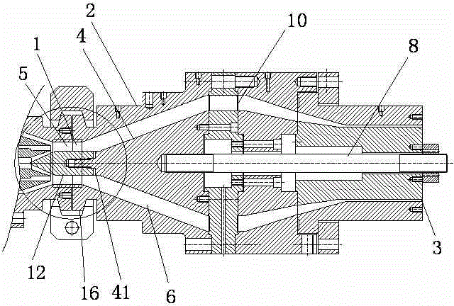
[0017] Embodiment 1: as Figure 1-2 As shown, a foam tube extrusion die with adjustable feed flow rate of the present invention includes a cylindrical die 2 extending transversely and a cylindrical mandrel 4 arranged in the die, between the die 2 and the mandrel 4 The tubular gap between them becomes the slurry channel 6, the axis of the mandrel 4 is provided with a mandrel 8 extending transversely, and the axial middle part is provided with a columnar support rod 10 connecting the mandrel 8 and the outer wall of the die 2, and the extrusion die The two ends in the transverse direction are the inlet port 1 and the outlet port 3 respectively. At the inlet port 1, the mandrel 4 is provided with a regulator 12 whose head is tapered and whose axial distance relative to the mandrel 4 is adjustable. The regulator 12 is connected to the mandrel 4 through screws 14, with the head facing outwards. The inlet end 1 is provided with a flange 16 for connecting with the feeding mold. Alon...

Embodiment 2

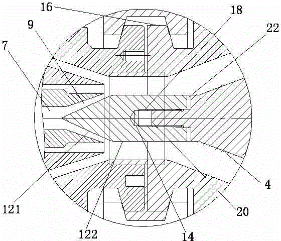
[0018] Embodiment 2 (not shown): The difference from Embodiment 1 is that the screws 14 are located along the radial direction of the mandrel 4, and the protrusions 20 of the mandrel 4 are provided with 3-4 axially located at different positions. The screw holes 24 are matched with the screws 14 respectively. When in use, the axial distance of the regulator 12 relative to the outlet end 3 of the feed mold is changed by inserting the screw 14 into different screw holes 24 .

[0019] When manufacturing the foam tube, the inlet end 1 of the extrusion die and the outlet end 5 of the feed die are connected through a flange, and the head 121 of the regulator 12 is inserted into the inner passage 7 of the feed die. Since the two ends of the usual inner passage 7 are Trumpet-shaped, so that the regulator head 121 is specifically inserted into the horn-shaped part 9 of the inner channel close to the outlet end 5 of the feed mould. Change the distance of the adjuster head 121 relative ...


PUM


Abstract

The invention relates to a foaming pipe extrusion die capable of adjusting the flow rate of a feeding material. The foaming pipe extrusion die comprises a tubular extrusion die which is transversely extended and a columnar core die which is arranged inside the extrusion die, wherein a tubular gap between the extrusion die and the core die becomes a slurry channel, a central spindle which is transversely extended is arranged on an axis of the core die, and a columnar supporting bar for connecting the central spindle with the outer wall of the extrusion die is arranged on the axial middle part. The foaming pipe extrusion die is characterized in that the transverse two ends of the foaming pipe extrusion die are an inlet end and an outlet end, an adjuster of which head of in a cone shape and an axial distance relative to the core die can be adjusted, is arranged on the core die at the inlet end, the adjuster is connected with the core die by bolts and the head of the core die is towards outside. According to the foaming pipe extrusion die, the adjuster of which the axial distance can be adjusted is arranged at the inlet end of the extrusion die, the outlet end flow rate of a channel inside a feeding die for matching use is changed, so that the flexible control of an operator is convenient, and the quality stability of the foaming pipe is guaranteed. An elastic sealing spacer can be arranged between the adjuster and the core die inlet end of the die, so that the sealing performance of the slurry channel can be guaranteed and metal connection components are protected.

Description

technical field [0001] The invention relates to a die for manufacturing plastic pipes, in particular to an extrusion die for manufacturing foam pipes. Background technique [0002] The production line of PVC foam pipe or PE foam pipe is composed of feeding die, extrusion die and other auxiliary mechanical equipment. The foamed pipe material includes a tubular body and an annular foam layer arranged in the middle of the body. Correspondingly, the pipe material slurry also includes the body slurry and the foam slurry wrapped in the body slurry. The feeding mold is equipped with inner and outer three-layer passages, in which the inner and outer passages use the body slurry, and the middle passage uses the foaming slurry. At the intersection end is the outlet end of the feeding mold, the inner and outer body slurry wraps the foaming slurry in the middle to form Pipe material slurry, because the slurry channel of the extrusion die is tubular, when the main body slurry in the inn...

Claims


Application Information

Patent Timeline
Patent Type & Authority Patents(China)
IPC IPC(8): B29C47/22B29C48/325
Inventor 苗海豹罗中山叶志勇张祥军张波
Owner 昆山圣源机械有限公司
Why Eureka
Try Eureka