Connecting rod combination structure for trolley

A connecting rod and trolley technology, which is applied in the field of connecting rod binding structures for trolleys, can solve the problems of broken elastic clips, falling off of locking protrusions, difficulty in pulling out and inserting connecting rods, etc., so as to reduce the resistance of insertion and extraction. , Improve the effect of supporting strength

Active Publication Date: 2015-12-09
SANKO CO LTD
View PDF7 Cites 0 Cited by
  • Summary
  • Abstract
  • Description
  • Claims
  • Application Information

AI Technical Summary

Problems solved by technology

[0005] In the above-mentioned connecting rod coupling structure for trolleys, since the elastic engaging piece is elastically deformed during the process of pulling out the connecting rod and inserting it into the insertion hole, when the elastic force of the elastic engaging piece is large, the pulling out and inserting operation of the connecting rod will be difficult. become difficult
However, when the elastic engaging piece is thinned, the width of the elastic engaging piece is narrowed, or the engagement between the locking protrusion and the locking recess is made shallow in order to facilitate the extraction and insertion operation, the holding of the connecting rod will be difficult. Under the action of tensile load, the elastic engaging piece is broken or deformed, and the locking protrusion is likely to fall off from the locking recess.

Method used


Image

  • Connecting rod combination structure for trolley
  • Connecting rod combination structure for trolley
  • Connecting rod combination structure for trolley

Examples


no. 1 approach

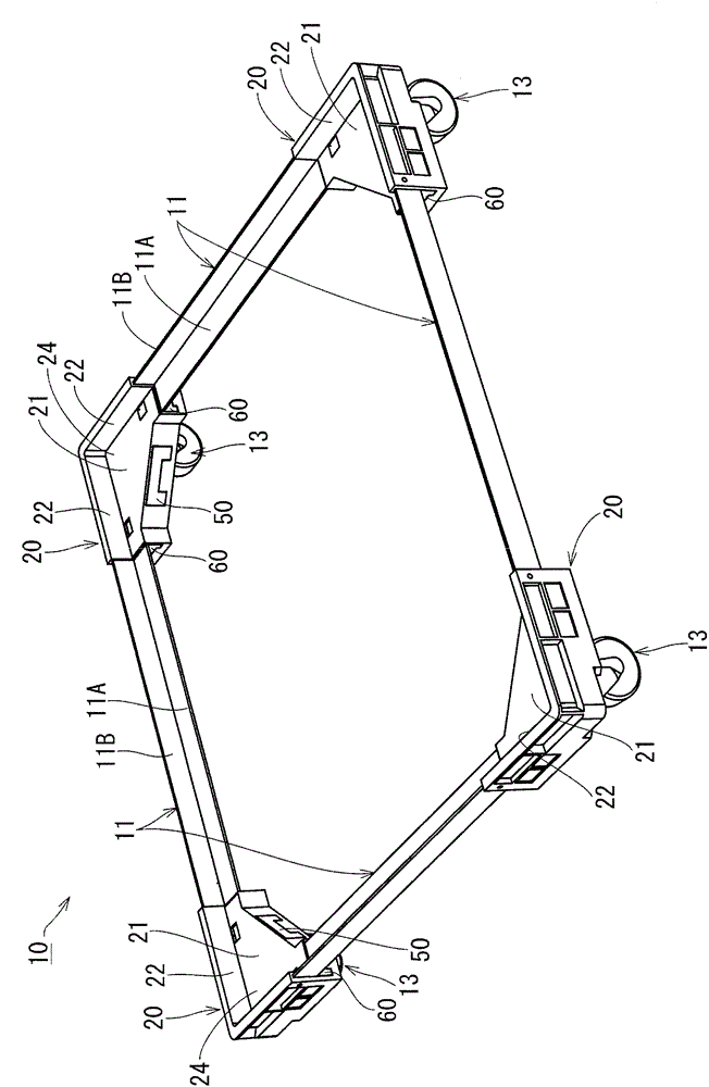
[0068] Below, based on Figure 1 to Figure 13 The first embodiment of the present invention will be described. figure 1 The trolley 10 shown has a quadrangular frame shape in plan view, and the trolley coupling structure of the present invention is used to connect the connecting rods 11 extending along the four sides and the support blocks 20 supporting the casters 13 at the four corners.

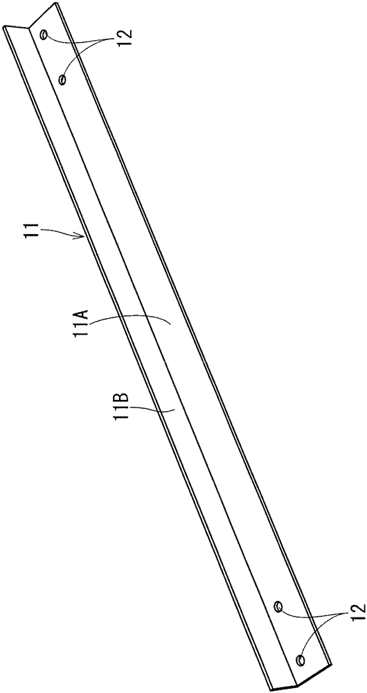
[0069] The connecting rod 11 is, for example, a so-called angle iron made of aluminum and has an L-shaped cross-section. A vertical plate portion 11B constituting a longitudinal side portion of the L-shape stands upright above a horizontal plate portion 11A constituting a lateral side portion. Such as figure 2 As shown, a pair of connecting through-holes 12 , 12 are respectively formed at both ends of the horizontal plate portion 11A of the connecting rod 11 . These connecting through-holes 12 , 12 are all circular holes arranged along the longitudinal direction of the connecting rod 11 ...

no. 2 approach

[0108] This embodiment is shown in Figure 14 ~ Figure 19 , is a structure in which the rod stopper 60 can be inserted into the rod insertion hole 41 from a direction different from that of the connecting rod 11 . That is, if Figure 14 As shown in (B), rod stopper insertion holes 46 , 46 communicating with the rod insertion hole 41 are respectively formed in the main side walls 26 , 26 of the support block 20V of this embodiment. The rod stopper insertion hole 46 has a horizontally long quadrangular shape as a whole, and has stepped recesses 46J, 46J sunken in steps at both ends of the lower portion of the opening. In addition, the rod stopper insertion hole 46 is located at a position below which the plate thickness of the rod 11 is connected with respect to the inner upper surface of the rod insertion hole 41 . The inner lower surface of the rod stopper insertion hole 46 excluding the step recesses 46J, 46J is flush with the inner lower surface of the rod insertion hole 4...

no. 3 approach

[0118] This embodiment is shown in Figure 20 ~ Figure 25 . The support block 20W of this embodiment is as Figure 20 ~ Figure 22 As shown, the caster stopper receiving portion 40W and the rod insertion holes 41, 41 are communicated in a wide range, and the caster stopper 50W is used as the caster stopper 50 and the rod stopper 60 of the first embodiment. , 60 structure. Specifically, as Figure 20 as well as Figure 21 As shown, the inner corner side walls 28 , 28 remain slightly in the form of columns on one side of the block front end faces 20T, 20T. Additionally, if Figure 22 As shown, the plate side support ribs 29B, 29B are cut out to the position in front of the communication hole 37 on the back side of the caster stopper storage part 40W than the insertion opening 40N of the caster stopper 50W in the caster stopper storage part 40W. .

[0119] In contrast, such as Figure 24 (A) and Figure 24 As shown in (B), the caster stopper 50W is formed in a structure i...


PUM


Abstract

A connecting rod joint structure used for a trolley which can firmly hold the connecting rod in a rod insert hole only by using a small operating force. According to the connecting rod joint structure used for the trolley of the invention, the joint teat (36) of the rod insert hole (41) is enabled to concave-convexly engage with the joint through hole (12) of the connecting rod (11). Thus, the resting wall part of the joint teat (36) of a rest pad (20) needs no generation of elastic deformation like existing elastic block sheets, therefore improving the supporting strength of the joint teat (36) of the rest pad (20), holding the connecting rod (11) in the rod insert hole (41) more firmly than before. Additionally, a rod retainer (60) doesn't bear forces from other structure units of the connecting rod (11) and the rest pad (20) in a direction of pulling out from hole inside space (41S), therefore reducing the blocking force of the elastic block sheet (63) used for holding the rod retainer (60) in the hole inside space (41S), and reducing the insert / pulling resistance of the rod retainer (60).

Description

technical field [0001] The present invention relates to a connecting rod coupling structure for a trolley, which holds connecting rods arranged on each side of a frame-shaped cart in a rod insertion hole of a support block on which casters are attached to the lower surface. Background technique [0002] At present, as such a connection rod connection structure for a trolley, there is known a structure in which the locking protrusions of the elastic locking piece provided in the rod insertion hole are engaged with the locking recesses of the connecting rod in a state where the concave and convex parts are engaged. The upper end base plate of the caster contacts the elastic locking piece to limit the elastic deformation of the elastic locking piece, thereby strengthening the engagement between the elastic locking piece and the connecting rod (for example, refer to Patent Document 1). [0003] patent documents [0004] Patent Document 1: Japanese Unexamined Patent Publication ...

Claims


Application Information

Patent Timeline
Patent Type & Authority Patents(China)
IPC IPC(8): B62B5/00
Inventor 春日一辉
Owner SANKO CO LTD
Why Eureka
Try Eureka