Metal product stacker

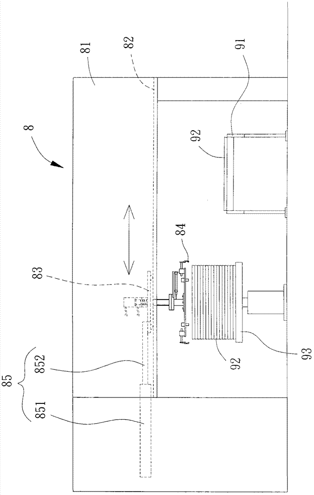
A technology of metal products and stacking machines, which is applied to the stacking, transportation and packaging of objects, and can solve the problems of large size of the frame body 81, easy damage of the pneumatic cylinder 85, and space occupation, so as to solve the impact of high temperature environment and avoid travel Error, the effect of improving stacking efficiency

Inactive Publication Date: 2012-12-12
TAI WEI MACHINE
View PDF7 Cites 3 Cited by
  • Summary
  • Abstract
  • Description
  • Claims
  • Application Information

AI Technical Summary

Problems solved by technology

[0004] Since the frame body 81 is in the shape of a ㄇ and is set across the conveyor belt 91, a space must be reserved for the frame body 81 on both sides of the conveyor belt 91, and the pneumatic cylinder 85 is composed of a cylinder 851 and a piston rod 852, the piston rod 852 can be relatively retracted or stretched out of the cylinder 851, when the movable stroke of the slide seat 83 and clamp 84 is longer, the length of the cylinder 851 and the piston rod 852 is relatively longer long, and when the piston rod 852 is in the state of stretching out the cylinder 851, the total length of the cylinder 851 and the piston rod 852 is almost twice the movable stroke of the slide seat 83 and the clamp 84, so the existing The frame body 81 of the metal product stacker 8 must reserve a large space for accommodating the pneumatic cylinder 85, causing the frame body 81 of the existing metal product stacker 8 to have the disadvantages of large volume and space occupation
[0005] Moreover, the sliding seat 83 and the clamp 84 of the existing metal product stacker 8 reciprocate in a straight line, so the moving stroke is relatively long, making the stacking efficiency relatively poor.
Although this existing structure utilizes the characteristics of the fast moving speed of the piston rod 852 of the pneumatic cylinder 85, the stacking action can be accelerated, but the pneumatic cylinder 85 itself also has the disadvantage of not being resistant to high temperatures, and the metal product 92 that has just been cast is still fragile. The high temperature of 300-400°C makes the pneumatic cylinder 85 vulnerable to the high temperature of the metal product 92 and is easily damaged
Furthermore, the action of the piston rod 852 retracting into or extending out of the cylinder 851 is driven by gas. When the pneumatic cylinder 85 is in a high-temperature environment, the gas is easily affected by the thermal expansion and contraction of the temperature, resulting in the The stroke error of the piston rod 852, which in turn leads to the stroke error of the slide seat 83 and the clamp 84

Method used


Image

  • Metal product stacker
  • Metal product stacker
  • Metal product stacker

Examples


Embodiment Construction

[0032] In order to make the above-mentioned and other objects, features and advantages of the present invention more comprehensible, the preferred embodiments of the present invention are specifically cited below, together with the accompanying drawings, as follows:

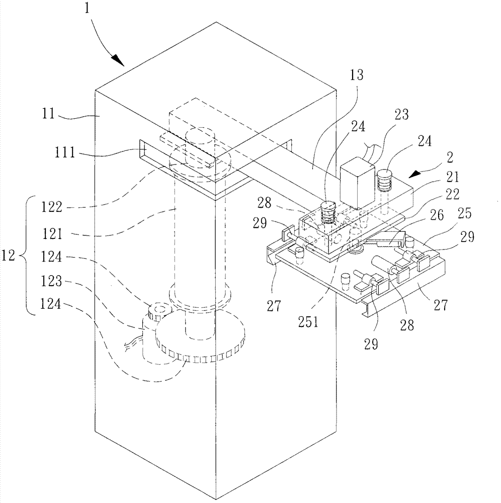
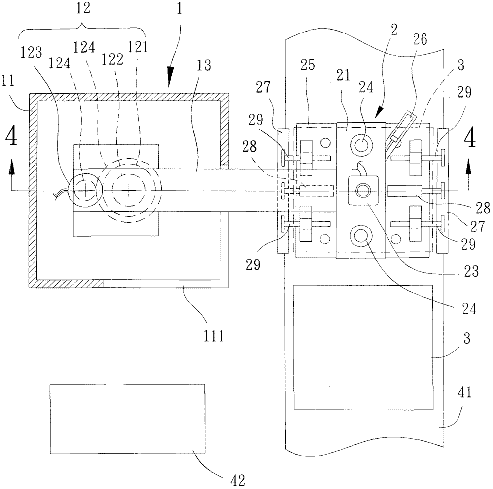
[0033] Please refer to figure 2 and 3 As shown, the metal product stacker of the present invention includes a machine table 1 and a clamping device 2 . Wherein the clamping device 2 is arranged on the machine table 1 and can be used for clamping the metal product 3 .

[0034] The machine 1 is provided with a driving device 12 in a casing 11. The driving device 12 can be fixed with a sleeve 121 in the casing 11. A rotating shaft 122 is pierced in the center of the sleeve 121. The rotating shaft 122 Each of the two ends protrudes from the two ends of the sleeve 121, and can rotate relative to the sleeve 121, and the top of the rotating shaft 122 is combined with the first end of a swing arm 13, and the casing 11...


PUM


Abstract

A metal product stacker, comprises: a table having a drive device which is connected to a first end of a swing arm, and the drive device drives the swing arm to rotate at an angle and reset; and a gripping device having a fixing member, the fixing member is provided on a second end of the swing arm. A lift member is liftablely provided below the fixing member. A rotary member is rotatably disposed below the lift member, and the rotary member has two grip members which can open and close relative to each other. The metal product stacker of the present invention, the drive device drives the swing arm to rotate at an angle, enabling the second end of the gripping device to repeatedly move, and thus shortening the moving distance of the gripping device, reducing the time consumed by the moving distance of the gripping device, and improving stacking efficiency.

Description

technical field [0001] The invention relates to a metal product stacking machine, in particular to a metal product stacking machine for removing metal products from a conveyor belt and stacking them to facilitate subsequent loading and transportation. Background technique [0002] Please refer to figure 1 As shown, the existing metal product stacker 8 has a frame body 81 in the shape of an ㄇ, on which there is a guide rail 82, and the guide rail 82 is movably provided with a slide seat 83, which is combined with There is a clamp 84 , and a pneumatic cylinder 85 is disposed between the sliding seat 83 and the frame body 81 , and the pneumatic cylinder 85 can drive the sliding seat 83 to reciprocate along the guide rail 82 . [0003] The frame body 81 of the existing metal product stacker 8 spans above a conveyor belt 91, and the conveyor belt 91 is used to transport the cast metal products 92. The pneumatic cylinder 85 can drive the sliding seat 83 and the clamp 84 to move ...

Claims


Application Information

Patent Timeline
Patent Type & Authority Applications(China)
IPC IPC(8): B65G57/04
Inventor 方荣兴方士玮
Owner TAI WEI MACHINE
Why Eureka
Try Eureka