Backpressure valve capable of achieving automatic slurry injecting

A self-grouting and mud backflow technology, applied in wellbore/well components, earthwork drilling, wellbore flushing, etc., can solve problems such as large amount of engineering, plugging water holes, broken valve stems, etc., to reduce grouting costs, The effect of preventing the back injection of mud and reducing the amount of work

Active Publication Date: 2017-02-15
CHENGDU ZHUOXIN IND
View PDF11 Cites 3 Cited by
  • Summary
  • Abstract
  • Description
  • Claims
  • Application Information

AI Technical Summary

Problems solved by technology

[0005] 1. When running in the drill, every time a part of the drill pipe is put down, it is necessary to connect the grouting device to pour the mud into the drill pipe. After the grouting is completed, remove the grouting device and put it into the next section of the drill pipe. Repeat this to complete the drilling action , the project volume is very large, time-consuming and labor-intensive, a large amount of mud needs to be poured, and the cost of grouting is high
[0006] 2. A spring is installed between the valve core and the base of the back pressure valve. The spring is sleeved on the valve stem of the valve core. One end of the spring is connected to the base, and the other end is connected to the tapered block of the valve core. The diameter of the back pressure valve is small. During the long-term use of the back pressure, the valve core will move up and down, and the spring will continue to return and compress. Quick, effective and accurate reset cannot fit well with the taper surface of the valve seat, thus failing to achieve the purpose of blocking the water eye; and when the spring is compressed and reset, the spring swings and continuously hits the valve stem of the valve core, causing the valve The rod breaks and the spool loses its function, causing the mud to spray back, resulting in extremely serious consequences

Method used


Image

  • Backpressure valve capable of achieving automatic slurry injecting
  • Backpressure valve capable of achieving automatic slurry injecting
  • Backpressure valve capable of achieving automatic slurry injecting

Examples


Embodiment 1

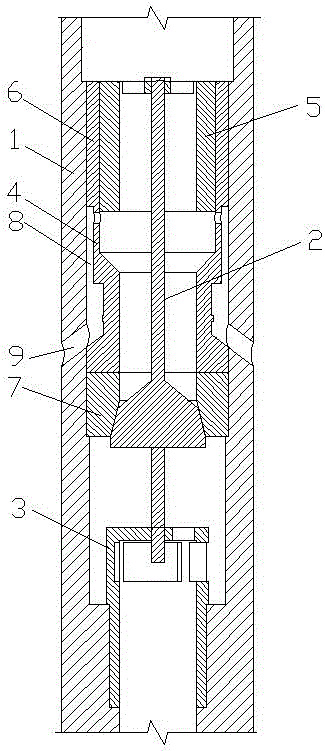
[0052] see figure 1 , a self-grouting back pressure valve, including a valve body 1, a valve core 2, a support seat 3 and a valve seat 4 arranged in the valve body 1, the support seat 3 is located below the valve seat 4, and the valve body 1 is set There is a piston 5, the piston 5 is set on the valve core 2, the valve seat 4 includes an upper valve seat 6 and a lower valve seat 7, the upper valve seat 6 is located between the piston 5 and the valve body 1, the upper valve seat 6 is provided with a mud return slot 8, and the mud return slot 8 communicates with the inner cavity of the valve body 1, and the valve body 1 is provided with a mud return hole 9, and the mud return slot 9 communicates with the mud return slot 8 .

[0053] This embodiment is the most basic implementation. A piston is arranged in the valve body, and the piston is sleeved on the valve core. The valve seat includes an upper valve seat and a lower valve seat. The upper valve seat is located between the pi...

Embodiment 2

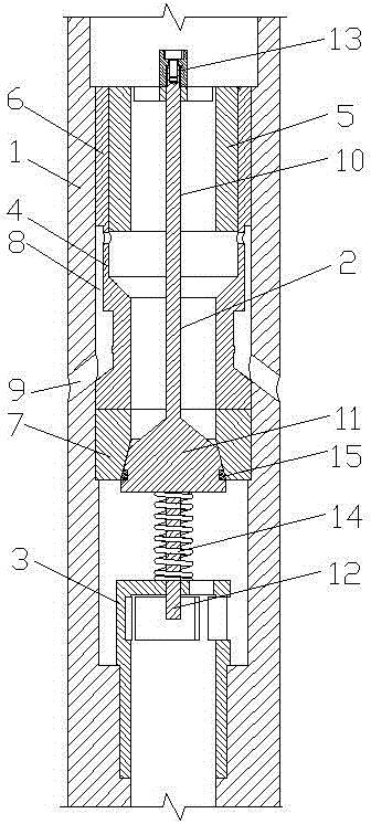
[0055] see figure 2 , a self-grouting back pressure valve, including a valve body 1, a valve core 2, a support seat 3 and a valve seat 4 arranged in the valve body 1, the support seat 3 is located below the valve seat 4, and the valve body 1 is set There is a piston 5, the piston 5 is set on the valve core 2, the valve seat 4 includes an upper valve seat 6 and a lower valve seat 7, the upper valve seat 6 is located between the piston 5 and the valve body 1, the upper valve seat 6 is provided with a mud return slot 8, and the mud return slot 8 communicates with the inner cavity of the valve body 1, and the valve body 1 is provided with a mud return hole 9, and the mud return slot 9 communicates with the mud return slot 8 .

[0056] Described spool 2 comprises upper valve stem 10, conical block 11 and lower valve stem 12 successively from top to bottom, and the upper end of upper valve stem 10 is provided with fixing nut 13, and the lower end is connected with the small end of...

Embodiment 3

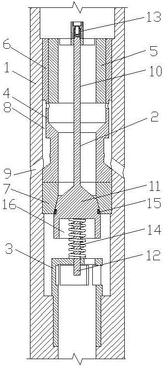
[0061] see image 3, a self-grouting back pressure valve, including a valve body 1, a valve core 2, a support seat 3 and a valve seat 4 arranged in the valve body 1, the support seat 3 is located below the valve seat 4, and the valve body 1 is set There is a piston 5, the piston 5 is set on the valve core 2, the valve seat 4 includes an upper valve seat 6 and a lower valve seat 7, the upper valve seat 6 is located between the piston 5 and the valve body 1, the upper valve seat 6 is provided with a mud return slot 8, and the mud return slot 8 communicates with the inner cavity of the valve body 1, and the valve body 1 is provided with a mud return hole 9, and the mud return slot 9 communicates with the mud return slot 8 .

[0062] Described spool 2 comprises upper valve stem 10, conical block 11 and lower valve stem 12 successively from top to bottom, and the upper end of upper valve stem 10 is provided with fixing nut 13, and the lower end is connected with the small end of c...


PUM


Abstract

The invention discloses a backpressure valve capable of achieving automatic slurry injecting, and belongs to the technical field of drilling equipment. The backpressure valve comprises a valve body, a valve element and a support base and a valve base which are arranged in the valve body, wherein the support base is located under the valve base. The backpressure valve is characterized in that a piston is arranged in the valve body and arranged on the valve element in a sleeving mode, the valve base comprises an upper valve base body and a lower valve base body, the upper valve base body is located between the piston and the valve body, a slurry reflux tank hole is formed in the upper valve base body and communicated with an inner cavity of the valve body, and a slurry reflux hole is formed in the valve body and communicated with the slurry reflux tank hole. According to the backpressure valve, due to the fact that slurry in a well can be automatically injected into a drill pipe and does not need to be injected into the drill pipe by connecting a slurry injection device to the drill pipe whenever a part of the drill pipe is put down, the work amount is greatly decreased, the slurry injecting cost is effectively reduced, the condition that the slurry in the well is reversely sprayed into the drill pipe through an inner cavity of the valve body is effectively prevented, and then well drilling safety is guaranteed.

Description

technical field [0001] The invention relates to the technical field of drilling equipment, in particular to a self-grouting back pressure valve. Background technique [0002] The back pressure valve is a device for preventing internal blowout during the drilling process. It is a check valve. The back pressure valve can effectively prevent the formation fluid from entering the drilling tool through the water hole of the drill bit. The existing back pressure valve mainly includes a valve body, a support seat, a valve core and a valve seat. Its structural principle is that there is a conical movable valve core in the water eye of the tool. When installing, its large end faces down and the small end faces upward. When the mud flows from the water eye to the top and bottom, the flow resistance is small and it can pass through smoothly; When the mud flows from the bottom to the top of the drill string, the large end receives a greater thrust, which prompts the conical movable dev...

Claims


Application Information

Patent Timeline
Patent Type & Authority Applications(China)
IPC IPC(8): E21B21/10
CPCE21B21/10
Inventor 陈伦俊池振华邹益文卢伟周强强刘飞鹏
Owner CHENGDU ZHUOXIN IND
Why Eureka
Try Eureka