Dry-type slag conveying device, slag removing apparatus, and slag removing method

A kind of slag discharge equipment and slag conveying technology, which is applied in the direction of lighting and heating equipment, etc., can solve the problem of low efficiency of ash discharge

Inactive Publication Date: 2012-12-12
BEIJING GUODIAN FUTONG SCI & TECH DEV +1
View PDF5 Cites 7 Cited by
  • Summary
  • Abstract
  • Description
  • Claims
  • Application Information

AI Technical Summary

Problems solved by technology

[0009] For this reason, what the present invention is to solve is the technical problem of low ash discharge efficiency in the prior art, and then proposes

Method used


Image

  • Dry-type slag conveying device, slag removing apparatus, and slag removing method
  • Dry-type slag conveying device, slag removing apparatus, and slag removing method
  • Dry-type slag conveying device, slag removing apparatus, and slag removing method

Examples


Embodiment 1

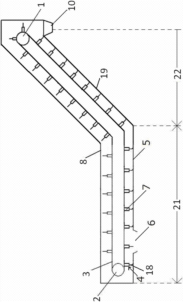
[0070] Such as figure 1 A dry slag conveying device of this embodiment is shown, wherein the dry slag conveying device is arranged inside the box body 8 of the slag discharge equipment, and is used to cooperate with the box body 8, wherein the The box body 8 of the slagging equipment includes a box body collection section 21 arranged below the boiler slag discharge port 9, and a box body delivery section 22 connected to the box body collection section 21 at one end, and the box body delivery section 22 The other end has a slag outlet 10 located at a high position. The angle between the bottom bearing surface 19 of the box body and the horizontal plane of the box body conveying section 22 is smaller than the angle of repose of fine ash. In this embodiment, the box body of the box body conveying section 22 The angle between the bearing surface 19 at the bottom of the body and the horizontal plane is 35 degrees.

[0071] The dry slag conveying device includes a first roller devi...

Embodiment 2

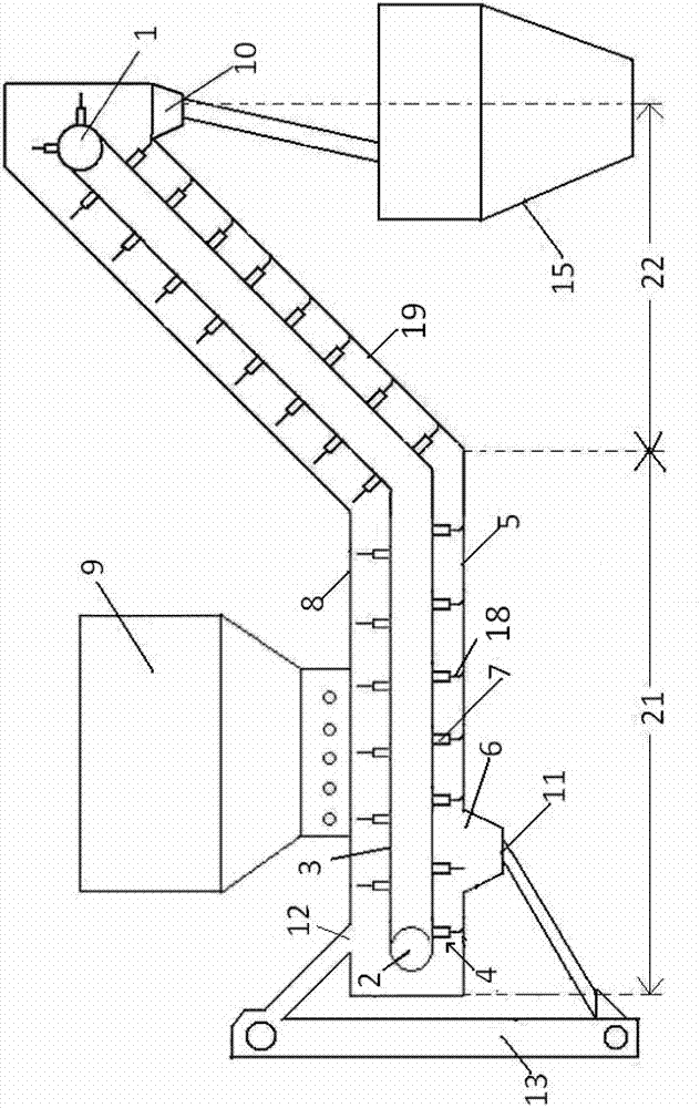
[0075] Such as image 3 It is a schematic diagram of a slagging equipment, which includes a box 8, the box 8 includes a box collection section 21 arranged below the boiler slag outlet 9, and one end is connected to the box collection section 21 The connected box conveying section 22, the other end of the box conveying section 22 has a slag outlet 10, and the box collecting section 21 is formed on the bottom bearing surface 19 of the box away from the box conveying section 22. The fine ash outlet 6, the included angle between the box bottom bearing surface 19 of the box conveying section 22 and the horizontal plane is smaller than the fine ash repose angle, and the included angle in this embodiment is 30 degrees.

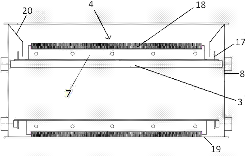
[0076] Wherein, the slag conveying device is installed inside the box body 8, including a first roller device 1, a second roller device 2, and a conveyor belt 3; wherein, the first roller device 1 and the second roller device 2 are respectively It is arranged at bot...

Embodiment 3

[0084] As another alternative embodiment of the slagging equipment of the present invention, such as Figure 4 As shown, a box body 8 is included, and the box body 8 includes a box body collection section 21 arranged below the boiler slag outlet 9, and a box body conveying section 22 connected to the box body collection section 21 at one end, the box body The other end of the body conveying section 22 has a slag discharge port 10 located at a high position, and a fine ash outlet 6 is formed on the bottom bearing surface 5 of the box body at the end of the box body collecting section 21 away from the box body conveying section 22, and the box body collection section 21 is formed with a fine ash outlet 6. The included angle between the bearing surface 19 of the box bottom of the body conveying section 22 and the horizontal plane is smaller than the angle of repose of the fine ash, and the included angle in this embodiment is 25 degrees.

[0085] The above-mentioned slagging equi...


PUM


Abstract

The invention relates to a dry-type slag conveying device, a slag removing apparatus and a slag removing method. The dry-type slag conveying device comprises a rigid brush device, wherein the rigid brush device is arranged on a slag receiving surface of a conveyor belt and is used for being matched a box-body bottom bearing surface of the slag removing apparatus; the fine dust on the box-body bottom bearing surface is driven by the back stroke movement of the conveyor belt to move towards a fine-dust outlet arranged on the bottom bearing surface, thereby taking the fine dust on the box-body bottom bearing surface arranged on the box-body conveying section away from the box-body bottom bearing surface of the box body conveying section. The dry-type slag conveying device is used in both the slag removing apparatus and the slag removing method. With the adoption of the slag removing apparatus and the slag removing method of the dry-type slag conveying device, the fine-dust removing efficiency can be improved.

Description

technical field [0001] The invention relates to the field of conveying and processing boiler slag, in particular to a dry slag conveying device, slag discharge equipment and a slag discharge method. Background technique [0002] When industrially performing dry-type slag discharge treatment on coal-fired boiler ash, it is necessary to discharge the boiler ash (including large ash and fine ash) from the bottom of the boiler, and lift the discharged ash to a high position by conveying. in the slag storage bin. The dry slag conveying device mainly involves a device for conveying large pieces of ash. The corresponding dry slagging equipment mainly includes a box body and a slag conveying device arranged in the box body. Wherein, the slag carrying box includes a collection section for collecting slag and a delivery section for transporting slag to the slag storage bin, and correspondingly, a slag conveying device installed inside the box, the slag conveying device is located at...

Claims


Application Information

Patent Timeline
IPC IPC(8): F23J1/06
Inventor 刘振强于谦王玉玮张晶夏春华
Owner BEIJING GUODIAN FUTONG SCI & TECH DEV
Why Eureka
Try Eureka