Heat insulation tank

A technology of heat insulation box and vacuum heat insulation panel, which is applied to lighting and heating equipment, household refrigeration devices, household appliances, etc., can solve the problems such as the reduction of the internal volume of the box body, the inability of the door 1 to be fully thinned, and the reduction of the depth of the box body.

Inactive Publication Date: 2012-12-12
TOSHIBA LIFESTYLE PROD & SERVICES CORP
View PDF17 Cites 30 Cited by
  • Summary
  • Abstract
  • Description
  • Claims
  • Application Information

AI Technical Summary

Problems solved by technology

[0009] However, the current status quo is that the door 1 of the above-mentioned conventional heat insulation box not only uses the vacuum heat insulation panel 4, but also uses the foamed polyurethane 5 together, and the heat insulation performance of the foamed polyurethane 5 is better than that of the vacuum heat insulation panel 4. poor, so correspondingly, the thickness of the foamed polyurethane 5 must be large, so the door 1 cannot be sufficiently thinned
And, accompanying this, there are also following disadvantages, that is, the depth of the box body is reduced, and the inner volume of the box body is reduced.

Method used


Image

  • Heat insulation tank
  • Heat insulation tank
  • Heat insulation tank

Examples


no. 1 Embodiment approach

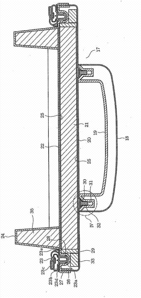
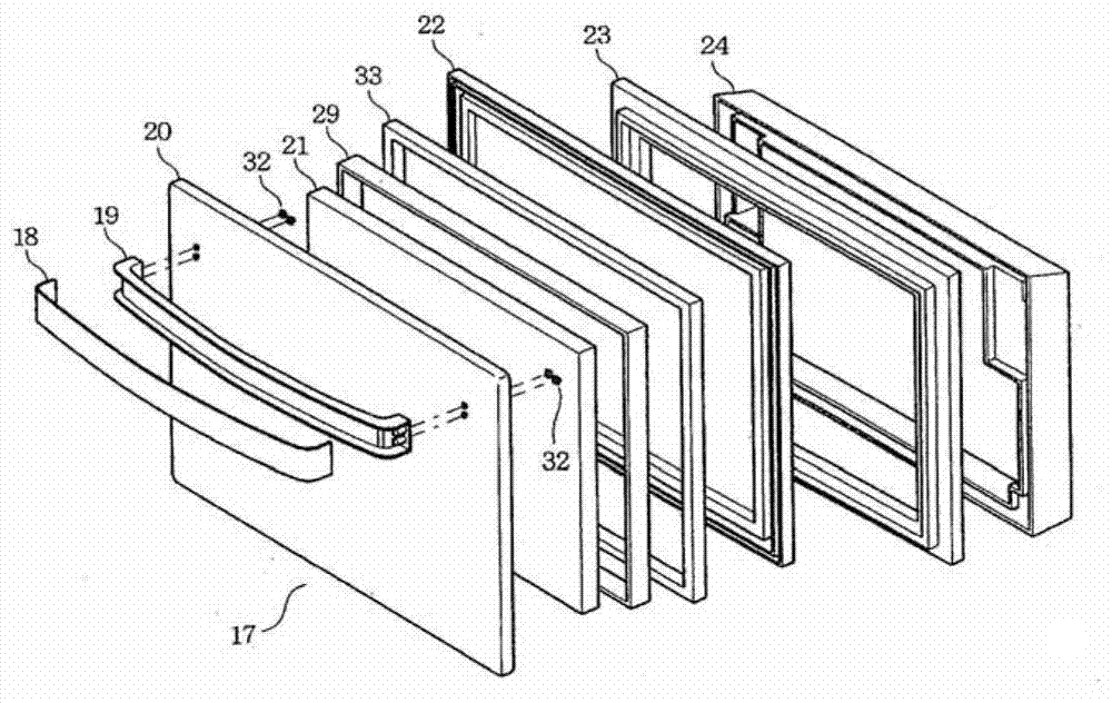
[0084] Below, refer to Figure 1 to Figure 4 The first embodiment applied to the refrigerator will be described.

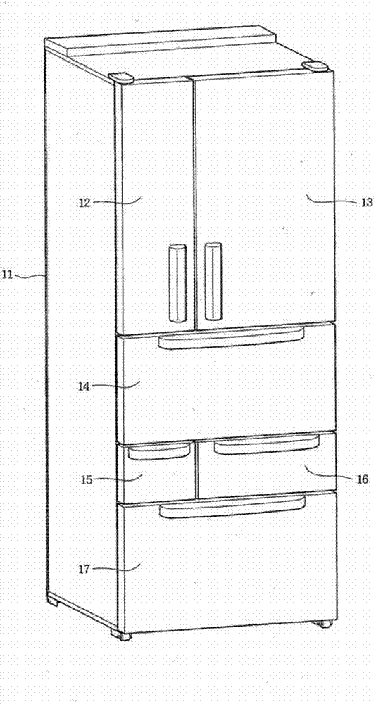
[0085] first, image 3 Showing the overall view of the refrigerator, the vertically long box-shaped box body 11 has a refrigerator compartment, a vegetable compartment, an ice-making compartment, a small freezer compartment, and a large freezer compartment (not shown), and has a refrigerator compartment door 12 on the front surface. , 13, vegetable compartment door 14, ice-making compartment door 15, small freezer compartment door 16, large freezer compartment door 17.

[0086]Among these doors 12 to 17, the refrigerator compartment doors 12 and 13 are French Type doors, the vegetable compartment door 14, the ice making compartment door 15, the small freezer compartment door 16, and the large freezer compartment door 17 are pull-out type. the door.

[0087] Then, in figure 1 and figure 2 In the drawing, any one of the drawer doors 14 to 17 is shown. In this...

no. 2 Embodiment approach

[0120] exist Figure 5 In the shown second embodiment, the door outer panel 41 is made of thick plastic instead of the door outer panel 20 of the first embodiment, and the both ends of the handle main body 19 are attached to the door outer panel 41 . Mounting holes 42 are formed in a funnel shape by die molding, and screw receiving holes 43 with flat openings are formed at both ends of the handle body 19 relative to the mounting holes 42 .

[0121] Under this structure, the handle main body 19 is mounted on the door outer panel 41 by screwing the screw 32 from the mounting hole 42 into the screw receiving hole 43 from the rear of the door outer panel 41 and tightening it.

[0122] In this case, the screw 32 will not be screwed into the part around the mounting hole 42 of the door outer panel 41, but will be submerged in the recess of the mounting hole 42, so that the screw 32 will not face the reverse installation direction from the rear surface of the door outer panel 41. Th...

no. 3 Embodiment approach

[0127] exist Figure 6 and Figure 7In the illustrated third embodiment, relatively large mounting holes 51 are formed in the portion of the door outer panel 41 where both ends of the handle main body 19 are mounted, and fasteners 52 are inserted into the mounting holes 51 .

[0128] The fastener 52 is a silk hat-shaped fastener having a flange portion 52b at the opening edge of a bottomed short cylindrical portion 52a, and the cylinder portion 52a of the fastener 52 is The rear side is inserted into the mounting hole 51 , and the flange portion 52 b is brought into contact with the rear surface of the peripheral portion of the mounting hole 51 .

[0129] Furthermore, the fastener 52 is provided with a screw hole 52c at the central portion of the bottom of the cylindrical portion 52a. At both ends of the handle body 19, screw receiving holes 53 having a size shorter than the screw receiving holes 43 of the second embodiment are formed.

[0130] Under this structure, from th...


PUM


Abstract

The invention provides a heat insulation tank which can achieve fully thinning doors of refrigerators, etc., thereby enabling the expansion of the inside volume of the tank body. For an outer door plate (20), the outer side surface of a vacuum insulation panel (21) is enabled to abut the rear surface of the outer door plate (20), and the front surface of the inner door plate (22) is enabled to abut the inner side surface of the vacuum insulation panel (21), thereby forming a large refrigerating room door (17) (door) without using foamed polyurethane. According to this structure, the fully thinning of the large refrigerating room door (17) can be achieved, thereby enabling the expansion of the inside volume of the tank body.

Description

technical field [0001] Embodiment of this invention relates to the heat insulation box, such as a refrigerator. Background technique [0002] Conventionally, heat insulating boxes of refrigerators and the like have doors. The door is generally composed of a door outer panel and a door inner panel, and foamed polyurethane (polyurethane) is filled between the two panels. However, the door of this structure only utilizes the thickness of the foamed polyurethane to obtain the required heat insulation performance, which has the disadvantage of a large door thickness. [0003] Furthermore, along with this, there is also a disadvantage that the depth of the box main body for accommodating stored goods is reduced in the entire heat-insulating box, that is, the inner volume of the box main body is reduced. [0004] In response to this, in recent years, doors using vacuum insulation panels have been provided. Doors using this vacuum insulated panel are as Figure 16 As shown in the...

Claims


Application Information

Patent Timeline
Patent Type & Authority Applications(China)
IPC IPC(8): F25D23/02
Inventor 阿部候巳佐伯友康石桥郁夫安部昌则
Owner TOSHIBA LIFESTYLE PROD & SERVICES CORP
Why Eureka
Try Eureka