
Method and magnetic resonance system for distortion correction in magnetic resonance imaging

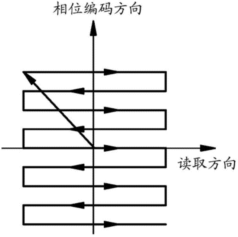
A technology for magnetic resonance imaging and distortion correction, which is applied to correct the distortion or deformation in the direction of phase encoding. In the field of magnetic resonance equipment, it can solve the problem that absolute value images cannot be directly compared with each other.

Inactive Publication Date: 2012-12-12
SIEMENS AG
View PDF9 Cites 9 Cited by
  • Summary
  • Abstract
  • Description
  • Claims
  • Application Information

AI Technical Summary

Problems solved by technology

Therefore the absolute value images cannot be directly compared to each other

Method used


Image

  • Method and magnetic resonance system for distortion correction in magnetic resonance imaging
  • Method and magnetic resonance system for distortion correction in magnetic resonance imaging
  • Method and magnetic resonance system for distortion correction in magnetic resonance imaging

Examples


Embodiment Construction

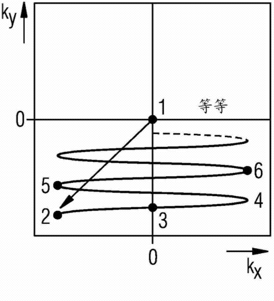
[0042] Figure 5 A trajectory 51 in the X / Y plane of the raw data space (so-called k-space) is shown. The trace 51 runs spirally from the outside to the inside and ends at the midpoint of the original data space. Data at points 52-57 are collected along trajectory 51 for filling the raw data space. There are other scanning points on the trajectory 51 , but these are not identified with reference numerals for the sake of clarity. There are also other scan points along the trajectory 51, but they are also not in the Figure 5 shown in . The other scanning points are distributed along the trajectory 51 up to the midpoint of the spiral trajectory 51 .

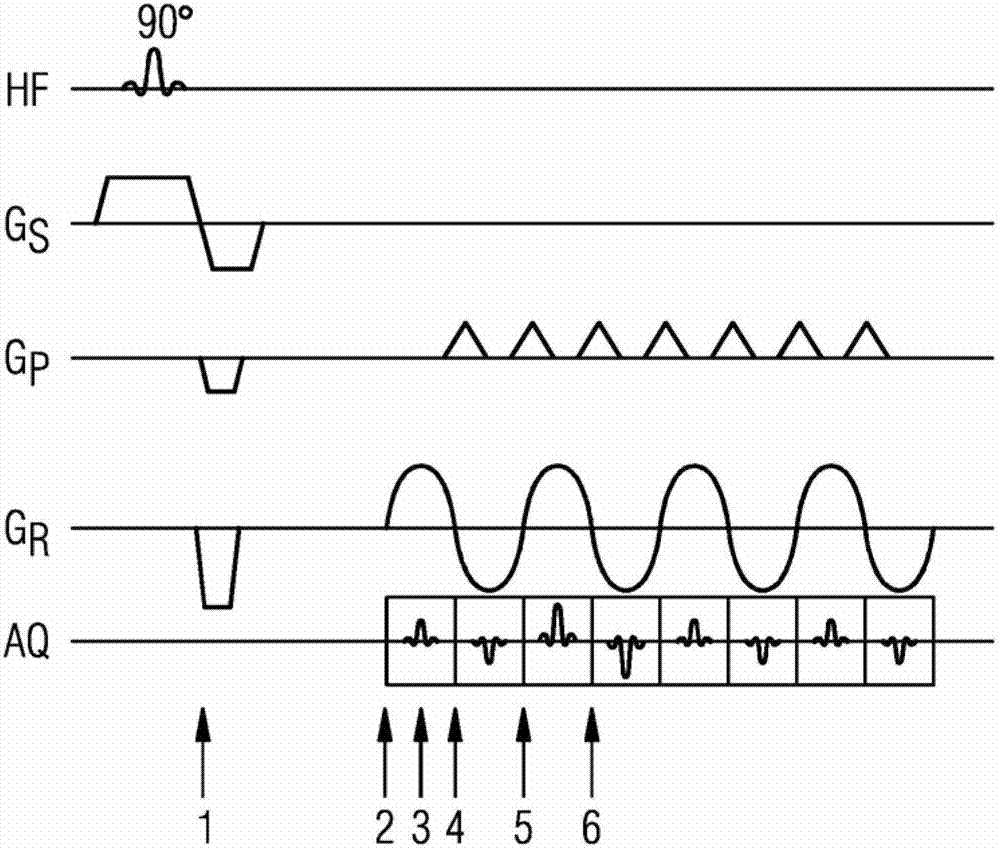
[0043] Figure 7 Show the gradient G x and G y sequence diagram, such as Figure 5 The shown spiral scans the raw data space. To do this, first an individual slice of the raw data space is selected and excited with radio-frequency pulses. The incentive is Figure 7 Not shown in detail, but schematically shown by box 61. ...


PUM


Abstract

The invention relates to a method for distortion correction in spiral magnetic resonance imaging, radial magnetic resonance imaging and echo planar imaging. In a method for distortion correction in spiral magnetic resonance imaging, a first MR data set is acquired by scanning raw data space along a spiral trajectory beginning at a first point. A first complex MR image is determined from the first MR data set, which includes first phase information for image points of the first MR image. A second MR data set is acquired by scanning raw data space along the spiral trajectory beginning at a second point that differs from the first point. A second complex MR image is determined from the second MR data set, which includes second phase information for image points of the second MR image. A geometric distortion for image points of the first or second MR image is determined from the first and second phase information, for example with a PLACE method.

Description

technical field [0001] The invention relates to a method for magnetic resonance imaging, as used in medical technology for examining patients. The invention relates in particular to a method for correcting distortions or deformations in the phase encoding direction which can occur in so-called EPI sequences using echo planes and other 2D or 3D imaging sequences and which can affect the image quality. [0002] The invention likewise relates to a correspondingly designed magnetic resonance system. Background technique [0003] Magnetic resonance tomography (MRT) for magnetic resonance imaging is based on the physical principle of nuclear spin resonance. In a magnetic resonance tomography system, an examination object, such as a patient, is exposed to a constant strong magnetic field. The nuclear spins of the atoms in the object thus have a certain orientation, whereas previously the nuclear spins were randomly oriented. High-frequency waves can excite these aligned nuclear ...

Claims


Application Information

Patent Timeline
Patent Type & Authority Applications(China)
IPC IPC(8): G01R33/565
CPCG01R33/5616G01R33/56572A61B5/055G01R33/4824G01R33/56554
Inventor J.法尤弗
Owner SIEMENS AG
Learn More