Three-phase power electronic transformer capable of balancing asymmetric load

An electronic transformer, three-phase power technology, applied in the direction of reducing the asymmetry of the polyphase network, eliminating/reducing the asymmetry of the polyphase network, etc. The effect of quality and operational reliability

Inactive Publication Date: 2012-12-12
XI AN JIAOTONG UNIV
View PDF6 Cites 7 Cited by
  • Summary
  • Abstract
  • Description
  • Claims
  • Application Information

AI Technical Summary

Problems solved by technology

[0004] At present, due to the relatively high cost of existing power electronic devices, the overall cost of power electronic transformers is much higher than that of traditional power transformers.

Method used


Image

  • Three-phase power electronic transformer capable of balancing asymmetric load
  • Three-phase power electronic transformer capable of balancing asymmetric load
  • Three-phase power electronic transformer capable of balancing asymmetric load

Examples


Embodiment 1

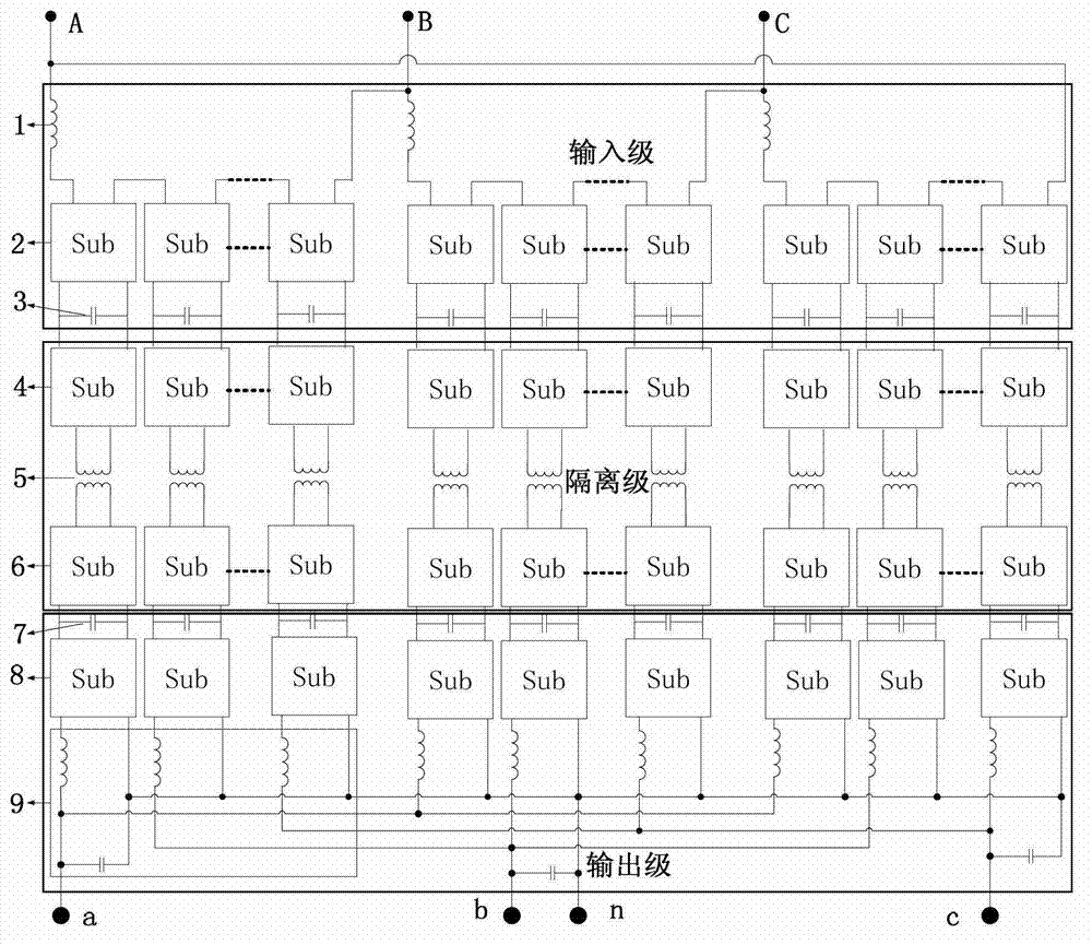
[0047] A three-phase power electronic transformer that can balance asymmetrical loads based on a multi-level multi-module cascaded structure adopts such as figure 1 The topological structure includes an input stage, an isolation stage, and an output stage, and the power converter of each stage includes two input terminals and two output terminals;

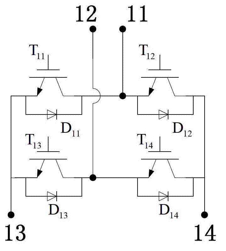
[0048] Specifically, each power converter is a fully-controlled single-phase full-bridge power converter composed of four fully-controlled devices, and its structure is as follows image 3 Shown is the fully controlled single-phase full-bridge power converter represented by Sub. The AC side of each phase of the power converter connected in series generally has a reactor connected in series to achieve harmonic suppression on the AC side. A capacitor bank with a certain capacity is connected in parallel between the two terminal lines of the DC side of the single-phase full-controlled bridge power converter.

[0049] Among the three...

Embodiment 2

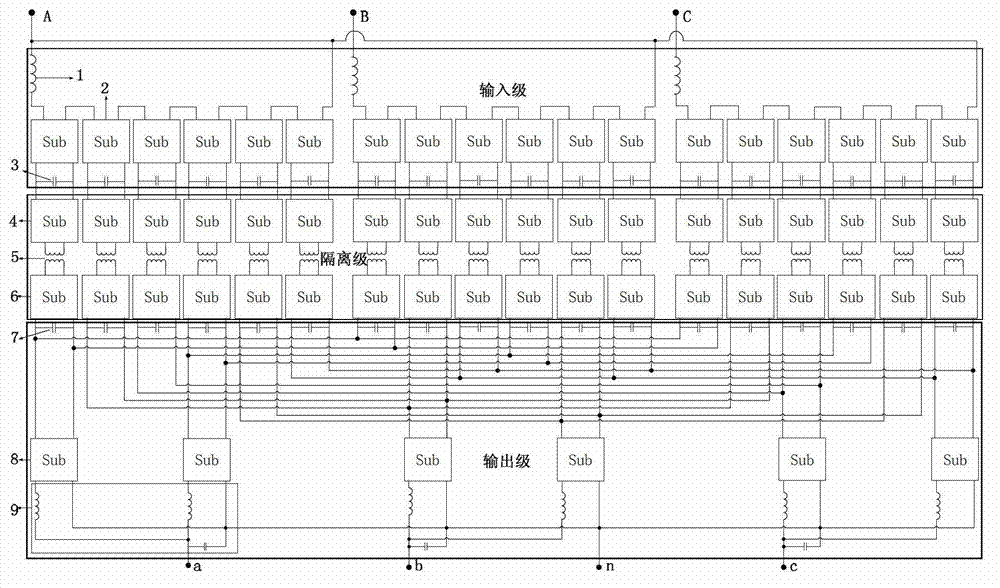
[0060] A three-phase power electronic transformer that can balance asymmetrical loads based on a multi-level multi-module cascaded structure adopts such as figure 2 The second topology shown includes an input stage, an isolation stage, and an output stage, and the power converter of each stage includes two input terminals and two output terminals;

[0061] The connection of the input stage and the isolation stage is the same as in Embodiment 1 and the number of power converters is changed to 6N, the difference is the connection of the output stage:

[0062] In the three phases of the output stage, each phase is provided with 2N output stage power converters 8, one for each phase of the three phases, and the output ends of the power converters 6 of the three high-frequency AC / DC links in the three phases are cross-connected and collected Afterwards, it is connected with the input end of an output stage power converter 8, and its output end is connected with an LC filter 9, and...


PUM


Abstract

The invention discloses a three-phase power electronic transformer capable of balancing asymmetric load. The transformer is divided into an input level, an isolation level and an output level, output ends of input-level power converters are connected with input ends of high-frequency DC (direct current)/AC (alternating current) link power converters, output ends of the high-frequency DC/AC link power converters are connected with primary sides of high-frequency transformers, secondary sides of the high-frequency transformers are connected with the input ends of the high-frequency DC/AC link power converters, the output ends of the high-frequency DC/AC link power converters are connected with input ends of output-level power converters, and output ends of the output-level power converters are connected with input ends of LC filters which are connected with a three-phase power supply network. The three-phase power electronic transformer capable of balancing asymmetric load can realize basic functions of transformation, isolation, energy transfer and the like of conventional power transformers, and as for input voltages of different levels, the serial module number of corresponding input levels only needs to be calculated, and corresponding voltage can be borne by serial connection according to corresponding module number.

Description

technical field [0001] The invention belongs to the technical field of power electronic transformers, and relates to a three-phase power electronic transformer capable of balancing asymmetrical loads based on a multi-stage multi-module cascade structure. Background technique [0002] In power systems, traditional power transformers, which are mainly used for voltage transformation and isolation, are widely used. On the one hand, the traditional power transformer has the advantages of high efficiency, low cost, high reliability, and simple structure; The environment poses a threat, the distorted current will pollute the grid when the load is nonlinear, and the load will be affected when the grid fluctuates, etc. With the development of power systems, especially the development of distributed power generation systems and new energy sources, there is an urgent need for a new power conversion device that can realize load-side voltage regulation, power factor correction, Harmon...

Claims


Application Information

Patent Timeline
Patent Type & Authority Applications(China)
IPC IPC(8): H02J3/26
CPCY02E40/50
Inventor 刘进军王新宇徐涛涛王晓剑
Owner XI AN JIAOTONG UNIV
Why Eureka
Try Eureka