Wireless charging device

A technology of wireless charging and resonant coils, which is applied in the direction of circuit devices, electrical components, electromagnetic wave systems, etc., can solve the problems of inconvenient wireless charging devices, unfavorable full use of electric energy, and obstacles to charging devices, so as to eliminate strong coupling phenomena and improve low-profile performance, guaranteed full utilization

Active Publication Date: 2015-06-10
STATE GRID CHONGQING ELECTRIC POWER CO ELECTRIC POWER RES INST +1
View PDF6 Cites 0 Cited by
  • Summary
  • Abstract
  • Description
  • Claims
  • Application Information

AI Technical Summary

Problems solved by technology

However, in the actual charging process, due to the influence between the external automotive metal equipment and the resonant coil, the automotive metal equipment may cause electromagnetic interference to the charging device, or even strong coupling, and over-coupling may also occur between the resonant coils. The resonant coil cannot work at a stable resonant frequency, which prevents the entire charging device from charging at a constant natural frequency, so that most of the power supply energy will be lost, the charging efficiency will be reduced, and the radiation efficiency will be increased, which is not conducive to the full utilization of electric energy , causing waste
[0004] Moreover, the receiving end of the wireless charging device located on the chassis of the car is designed with a thicker metal structure, which brings inconvenience to the actual installation of the wireless charging device

Method used


Image

  • Wireless charging device
  • Wireless charging device

Examples


Embodiment Construction

[0026] The following will clearly and completely describe the technical solutions in the embodiments of the present invention with reference to the accompanying drawings in the embodiments of the present invention. Obviously, the described embodiments are only some, not all, embodiments of the present invention. Based on the embodiments of the present invention, all other embodiments obtained by persons of ordinary skill in the art without creative efforts fall within the protection scope of the present invention.

[0027] The embodiment of the present invention discloses a wireless charging device to realize high-efficiency, low-radiation, and low-profile wireless charging of automobiles within a certain distance range.

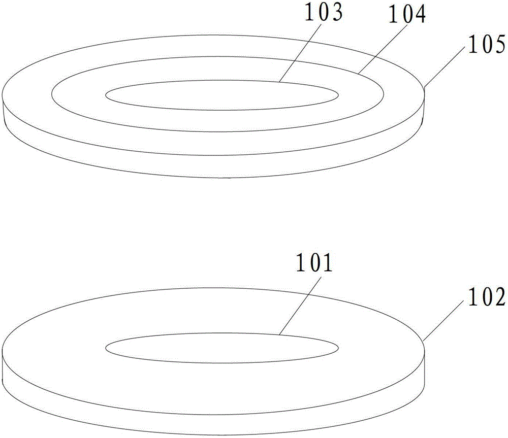
[0028] A wireless charging device such as figure 1 shown, including:

[0029] A first resonant coil 101 connected to an AC power supply and having a first characteristic index, the first resonant coil is located at the transmitting end;

[0030] A first el...


PUM


Abstract

The invention discloses a wireless charging device which comprises a first resonance coil, a second resonance coil, a first electromagnetic shielding cover, a second electromagnetic shielding cover and a load coil. The first resonance coil has first characteristic index and is located at the transmitting end. The second resonance coil has first characteristic index and located at the receiving end, and a preset distance is arranged between the first resonance coil and the second resonance coil. The first electromagnetic shielding cover covers the periphery of the first resonance coil and has first specific inherent attribute. The second electromagnetic shielding cover covers the periphery of the second resonance coil and the load coil and has first specific inherent attribute. The load coil is located on the same plane with the second resonance coil and on the periphery of the second resonance coil. The load coil is connected with an external device to couple electric energy carried by the second resonance coil. The first characterized index and the first specific inherent attribute are calculated according to preset distance and preset frequency. The preset frequency is resonance frequency of the first resonance coil and the second resonance coil. The wireless charging device can achieve high-efficiency low-radiation low-section wireless charging of automobiles in a certain distance range.

Description

technical field [0001] The invention relates to the field of wireless charging for electric vehicles, and more specifically, to a wireless charging device. Background technique [0002] With the development of power electronics technology, the research on electric vehicle charging technology has become a difficult point in the application of electric vehicles and a hot spot in the field of science and technology. Compared with the traditional contact charging technology, the wireless charging technology that has emerged in recent years has the advantages of non-contact, no electric spark, low cost, and not easy to enter water, which makes wireless charging technology more potential in the field of car charging. [0003] At present, the magnetic coupling charging technology mainly used in wireless charging technology is a relatively new wireless power supply technology that has emerged in recent years. , to achieve energy transfer. Compared with other wireless power supply ...

Claims


Application Information

Patent Timeline
Patent Type & Authority Patents(China)
IPC IPC(8): H02J17/00H05K9/00H02J50/12
Inventor 刘永相周全李林霞郑可欧习洋孙洪亮冯凌杨泽伟
Owner STATE GRID CHONGQING ELECTRIC POWER CO ELECTRIC POWER RES INST
Why Eureka
Try Eureka