
Magnetic governor with remote automatic control of radial air gap

A radial air gap and governor technology, applied in electrical components, electric components, electromechanical transmissions, etc., can solve problems such as failure and motor heating, and achieve the effects of reducing loss, improving efficiency, and improving utilization

Inactive Publication Date: 2012-12-12
JIANGSU UNIV
View PDF3 Cites 4 Cited by
  • Summary
  • Abstract
  • Description
  • Claims
  • Application Information

AI Technical Summary

Problems solved by technology

[0006] The invention provides a magnetic governor for remote and automatic radial air gap control. Through the research on the speed regulation structure, it not only realizes the purpose of the stepless speed change of the coupling itself, improves the transmission efficiency of the magnetic coupling, but also improves the transmission efficiency of the magnetic coupling. It solves the problem of motor heating and even failure due to excessive induction current when the motor load is started, and realizes the soft start function of the motor; through the research on the transmission mechanism composed of the inner and outer rotor assemblies, it proposes a motor that can provide stable rotation in different occasions. The transmission mechanism of torque and power expands the scope of use of magnetic couplings

Method used


Image

  • Magnetic governor with remote automatic control of radial air gap
  • Magnetic governor with remote automatic control of radial air gap
  • Magnetic governor with remote automatic control of radial air gap

Examples


Embodiment 1

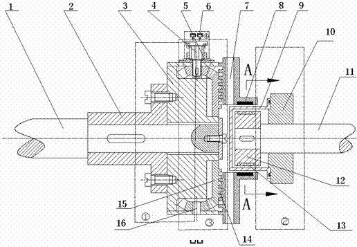
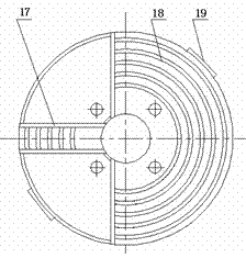
[0035] The working principle of Embodiment 1: when the step controller 20 sends a forward rotation signal, the stepper driver 23 receives a forward rotation pulse signal, and it drives the stepper motor 4 to rotate in the forward direction, and the stepper motor 4 drives the small cone The gear 16 rotates clockwise, the small bevel gear 16 drives the large bevel gear 15 to rotate counterclockwise, and the plane thread 18 on the back side also rotates counterclockwise, and the movable card body 7 is driven along the chute through the thread transmission. Move toward the radial straight line of the center of disc body 3, the radial distance between permanent magnet 8 and guide bar 13 becomes smaller, the magnetic field force between the air gap becomes larger, and the torque of output becomes larger; when stepping controller 20 sends When the reverse signal is received, the stepper driver 23 receives a reverse pulse signal, and it drives the stepper motor 4 to rotate in the oppo...

Embodiment 2

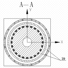
[0037] The working principle of embodiment 2: on the basis of embodiment 1, the guide bar 13 in the inner rotor assembly is replaced with the outer layer copper skin 30 wrapped on the inner layer solid rotor 31, when the step controller 20 sends a positive When turning the signal, the stepping driver 23 receives a positive rotation pulse signal, and it drives the stepping motor 4 to rotate in the positive direction, and the stepping motor 4 drives the small bevel gear 16 to rotate clockwise, and the small bevel gear 16 drives the large bevel gear 15 Rotate counterclockwise, and the flat thread 18 on the back side also rotates counterclockwise, and the movable card body 7 is driven along the chute through the screw drive. Move toward the center of the disc body 3 in a straight line radially, the radial distance between the permanent magnet 8 and the outer copper skin 30 becomes smaller, the magnetic field force between the air gap becomes larger, and the output torque becomes l...


PUM


Abstract

The invention relates to the field for the transmission technology of mechanical engineering, specifically to a magnetic governor with remote automatic control of radial air gap, wherein the rotation and displacement of a stepper motor is accurately controlled by controlling impulse frequency, the radial displacement of a movable clamping body is controlled by means of gear transmission and thread transmission, the radial distance between a permanent magnet and a conducting bar can be adjusted accurately, different rotate speed and torque are output, and the purpose of stepless speed change of a coupler is achieved.

Description

technical field [0001] The invention relates to the technical field of mechanical engineering transmission, in particular to a magnetic governor for remote and automatic radial air gap control, which is mainly used for power transmission between motors and loads in industries such as oil refining, chemical industry, coal, and power generation, and other devices . technical background [0002] In the field of mechanical engineering transmission technology, the coupling is an important part of the mechanical transmission system. With the continuous development of science and technology, the application range of the coupling is becoming wider and wider; in the traditional mechanical transmission system, due to the The mechanical connection method requires high centering accuracy between devices, which is very difficult for large-scale equipment or high-precision transmission systems. Once there is an error in the alignment, the transmission system may be twisted during work. T...

Claims


Application Information

Patent Timeline
IPC IPC(8): H02K51/00
Inventor 杨超君周曰华
Owner JIANGSU UNIV
Learn More