Magnetic rotary encoder

A rotary encoder and magnetic technology, applied in the direction of converting sensor output, instruments, measuring devices, etc., can solve the problems of increased noise in weak magnetic fields, non-uniform magnetic fields, not very strong magnetic fields, etc., and achieve high magnetic field strength and good uniformity. Effect

Active Publication Date: 2012-12-12
AVAGO TECH INT SALES PTE LTD
View PDF7 Cites 9 Cited by
  • Summary
  • Abstract
  • Description
  • Claims
  • Application Information

AI Technical Summary

Problems solved by technology

[0003] In this regard, if a single bipolar permanent magnet is used, the following disadvantages result: This arrangement only allows the use of the return or so-called leakage field of the permanent magnet, which is neither a homogeneous field nor an extremely strong field, let alone a magnetic field. Linear with rotation angle
In particular, the low field strength of the stray fields used has been found to be a significant obstacle, since weak fields require high levels of electrical amplification and thus lead to increased noise

Method used


Image

  • Magnetic rotary encoder
  • Magnetic rotary encoder
  • Magnetic rotary encoder

Examples


Embodiment Construction

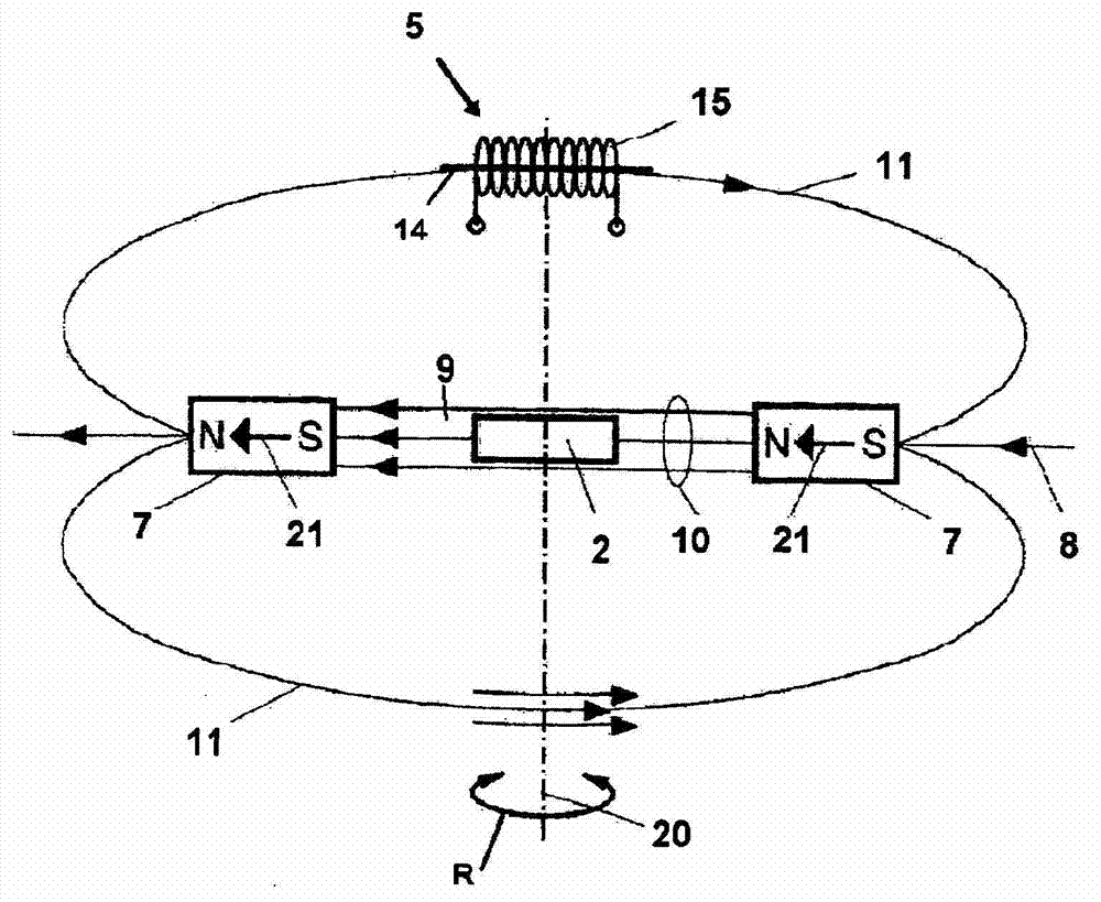
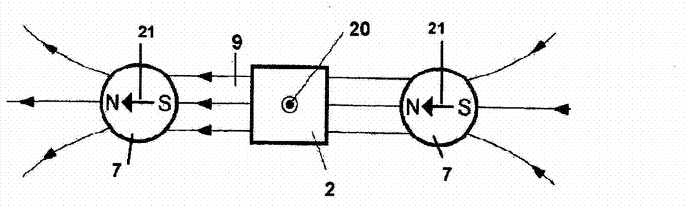
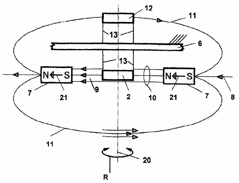
[0036] It should be emphasized that the drawings are not true to scale. The same elements in the various figures are denoted by the same reference numerals. exist figure 1 The rotary encoder denoted by reference numeral 8 in is an example of the first main variant discussed above, where it can be found in figure 1 as well as Figure 4 , 7 and 8 find an embodiment according to the first sub-variant, while in Figure 5 and 6 An example of the second sub-variant is shown in . Figure 9 and 10 An embodiment according to the second main variant is shown.

[0037] figure 1 Two first permanent magnets 7, 7 are shown whose magnetization vectors 21, 21 are aligned to each other so that they lie on a common straight line extending perpendicularly to the axis of rotation 20 of the rotary encoder 8 on. These two permanent magnets 7, 7 form an integral part of the excitation unit of the rotary encoder according to the invention, which is non-rotatably connected to a body (such as...


PUM


Abstract

The invention relates to a magnetic rotary encoder, comprising for fine resolution of the angle of rotation of a shaft (1) an exciter unit which images the rotation to be monitored and rotates about an axis of rotation (20), a stationary fine resolution sensor unit (2) for fine resolution of each resolution and an electronic processing unit. Said rotary encoder is characterised in that the exciter unit comprises two first permanent magnets (7, 7), which are disposed symmetrically with respect to the axis of rotation with mutual spacing so that the magnetisation vectors (21, 21) thereof extending through the respective centre of gravity extend in the same direction relative to the common field lines and form a central field space (9) which directly connects the permanent magnets, and that at least the fine resolution sensor unit is disposed in such a way that it can use the field (10) of the central field space for measurement.

Description

technical field [0001] The invention relates to a magnetic rotary encoder of the type stated in the preamble of claim 1 . Background technique [0002] EP 1243891B1 proposes a rotary encoder with an actuating element in the form of a permanent magnet which supplies the magnetic field required for the absolute measurement of fine position values, e.g. by means of a quadrant Hall This is achieved by a Hall probe whose Hall elements are connected in a cross relationship. In such cases, the amplitude and uniformity of the magnetic field play an important role. [0003] In this regard, if a single bipolar permanent magnet is used, the following disadvantages result: This arrangement only allows the use of the return or so-called leakage field of the permanent magnet, which is neither a homogeneous field nor an extremely strong field, let alone a magnetic field. It is linearly related to the rotation angle. In particular, the low field strength of the stray fields used has been...

Claims


Application Information

Patent Timeline
Patent Type & Authority Applications(China)
IPC IPC(8): G01D5/245
CPCG01D5/245G01D5/145G01D2205/40
Inventor W·梅纳特T·泰尔
Owner AVAGO TECH INT SALES PTE LTD
Why Eureka
Try Eureka