Porous perforating device

A technology of punching device and mounting plate, applied in metal processing and other directions, can solve the problems of inability to implement design and lack of multi-hole punching equipment.

Inactive Publication Date: 2012-12-19
CHINA INST OF WATER RESOURCES & HYDROPOWER RES +1
View PDF7 Cites 3 Cited by
  • Summary
  • Abstract
  • Description
  • Claims
  • Application Information

AI Technical Summary

Problems solved by technology

Due to the lack of corresponding multi-hole punc

Method used


Image

  • Porous perforating device
  • Porous perforating device

Examples


Embodiment Construction

[0025] In order to make the object, technical solution and advantages of the present invention clearer, the implementation manner of the present invention will be further described in detail below in conjunction with the accompanying drawings.

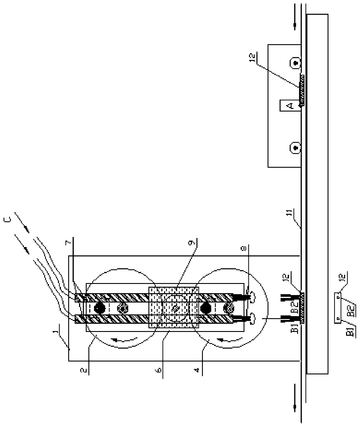
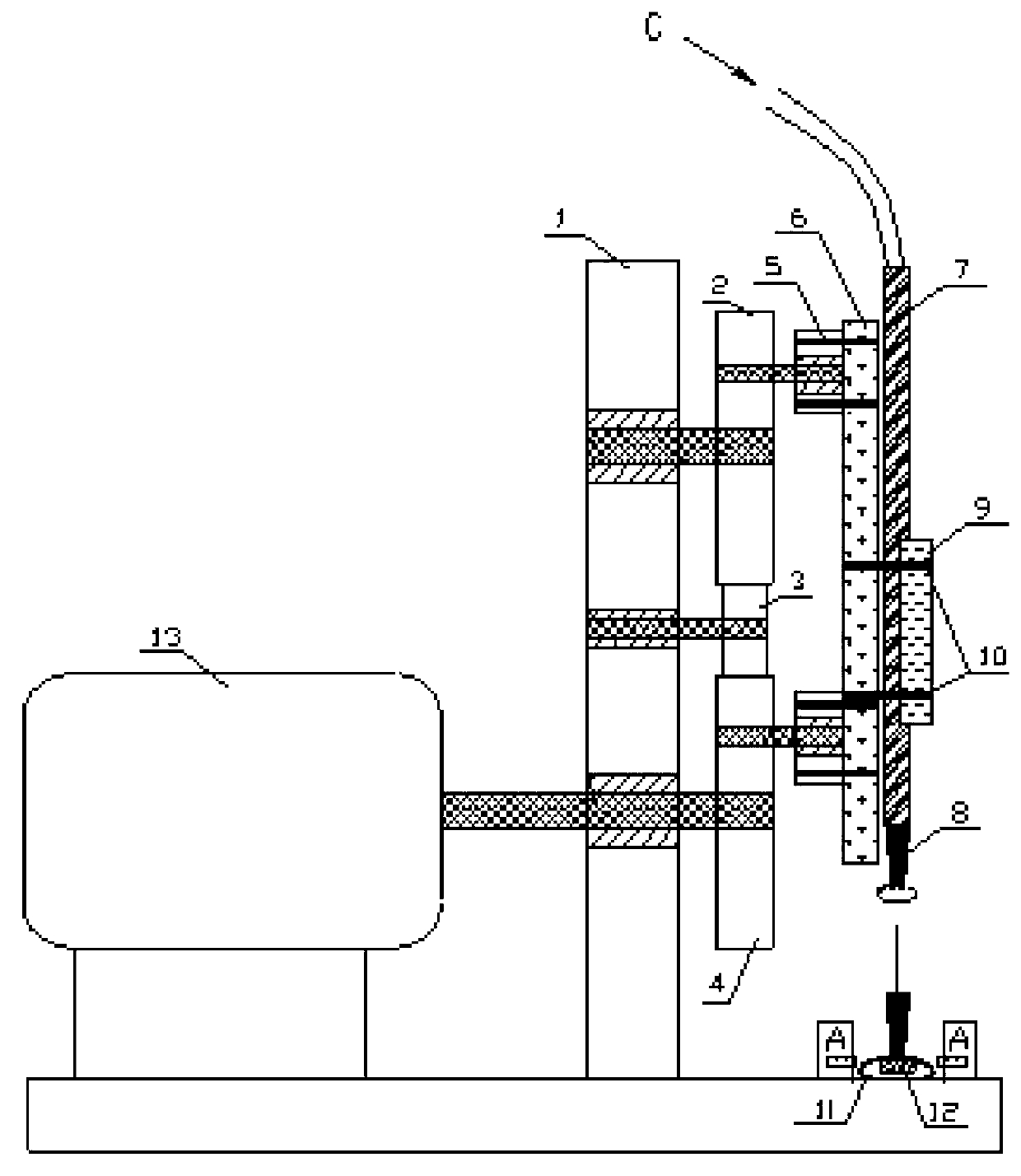
[0026] In this embodiment, two water outlet holes are punched on each dripper of the drip irrigation pipe as an example for illustration, but the multi-hole punching device of the present invention is not limited thereto, and the multi-hole punching device of the present invention is suitable for high-speed continuous The production line can punch out multiple orifices in a specific area according to the set distribution for long items.

[0027] Such as figure 1 As shown, a multi-hole punching device provided in an embodiment of the present invention is used to punch holes for articles, and the multi-hole punching device includes a motor 13, a transmission mechanism, an actuator and a track connected in sequence;

[0028] The transmis...


PUM


Abstract

The invention discloses a porous perforating device, belonging to the field of a perforating device. The device comprises an electric motor, a transmission mechanism, an executing mechanism and a rail which are connected sequentially. In work, the transmission mechanism is driven to move through the electric motor, and the transmission mechanism drives a cutter mounting plate to perform a composite translational movement in all rounds, thereby perforating an article passing through the rail. Each cutter in the device can always be in a vertical state in the process of perforating. When cutter bits come into contact with the article, each cutter bit comes into contact with the perforated article, and at least two holes are perforated in a specific zone according to the setting distribution. The device is especially suitable for the production line of a drop irrigation pipe in continuous running with high speed, and is capable of perforating at least two water outlets in the same one drop head of the drop irrigation pipe in continuous running with high speed.

Description

technical field [0001] The present invention relates to a high-speed punching device, in particular to a multi-hole punching device that can continuously punch multiple holes in a specific area at a high speed and according to a set distribution on the dripper of a drip irrigation pipe production line. device. Background technique [0002] my country is a country with scarce water resources, but the potential for saving agricultural water is great. Drip irrigation technology is a very effective water-saving irrigation measure. Using drip irrigation technology, the irrigation water can be evenly dripped to the root zone of the crops through the water outlet holes on the drip irrigation pipe, which minimizes the underground seepage loss and ground evaporation loss of irrigation water. [0003] The drip irrigation pipe is the key equipment in the drip irrigation project, including the pipe and the dripper embedded in the pipe, and the dripper is provided with a water outlet. ...

Claims


Application Information

Patent Timeline
IPC IPC(8): B26F1/02
Inventor 徐志昂杨继富李成秀江荣冷高占义沈应生赵忠福
Owner CHINA INST OF WATER RESOURCES & HYDROPOWER RES
Why Eureka
Try Eureka