Thrust device capable of balancing reactive torque

A thrust device and anti-torque technology, applied in the field of aerodynamics, can solve problems such as accidents, high accident rate, unsuitability for multi-flight mode rotary wing aircraft, etc., achieve high aerodynamic efficiency and increase flight speed

Active Publication Date: 2012-12-19
NORTHWESTERN POLYTECHNICAL UNIV
View PDF5 Cites 7 Cited by
  • Summary
  • Abstract
  • Description
  • Claims
  • Application Information

AI Technical Summary

Problems solved by technology

At present, there are coaxial double propellers, single rotor with tail rotor, etc., but for the rotary wing aircraft with multiple flight modes (application number is 201110213680.1), the rotor needs to be locked as a fixed wing during flight. , so the existing coaxial dual-propeller mode is not suitable for the above-mentioned rotary wing aircraft; and the tail rotor structure has a high accident rate of the tail rotor and the tail rotor drive system. When the rotorcraft is flying at low altitude or sticking to the ground, The high-speed rotating tail rotor is prone to problems such as collision with obstacles and accidents of ground personnel, and the tail rotor is still one of the vibration source and noise source of the rotorcraft. In addition, because a T-shaped tail needs to be installed at the rear of the rotary wing aircraft, Tail structure and tail rotor structure are prone to interference
Therefore, the existing structural forms of balanced anti-torque such as coaxial double propellers and single rotor with tail rotor are not suitable for rotary wing aircraft with multiple flight modes.

Method used


Image

  • Thrust device capable of balancing reactive torque
  • Thrust device capable of balancing reactive torque
  • Thrust device capable of balancing reactive torque

Examples


Embodiment Construction

[0019] The present invention is specifically described below in conjunction with embodiment:

[0020] This embodiment is an anti-torque thrust device used on a rotary wing aircraft, and the whole device is installed at the tail of the rotary wing aircraft.

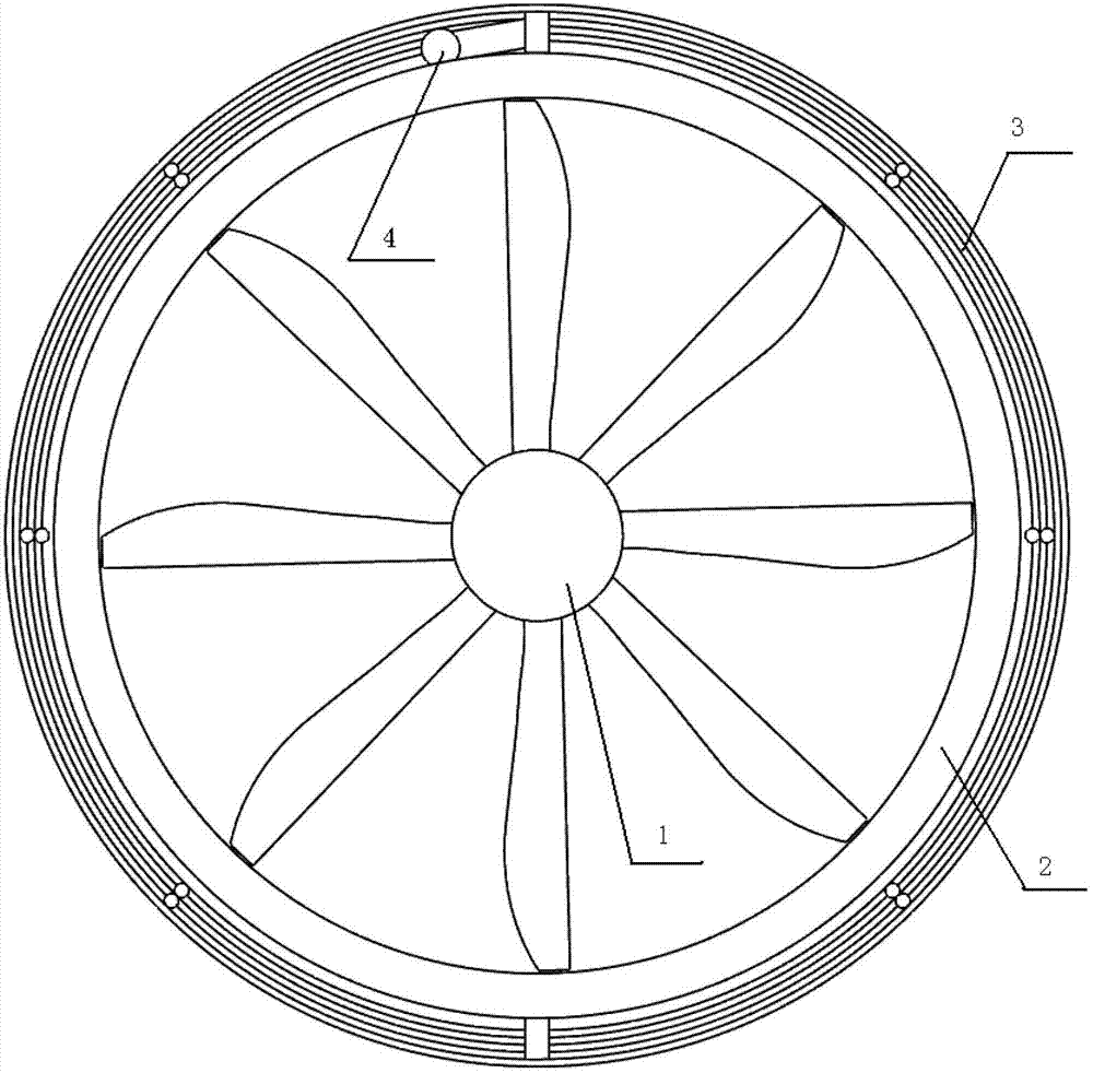
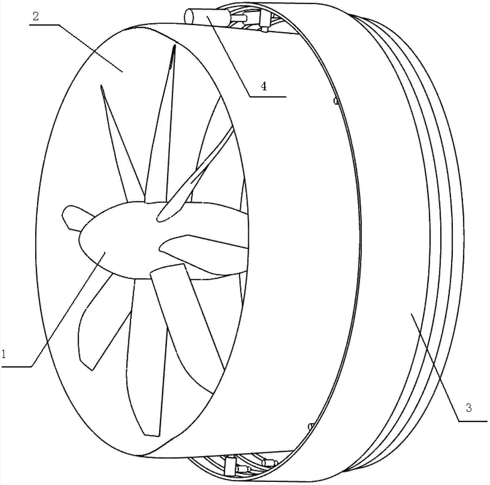
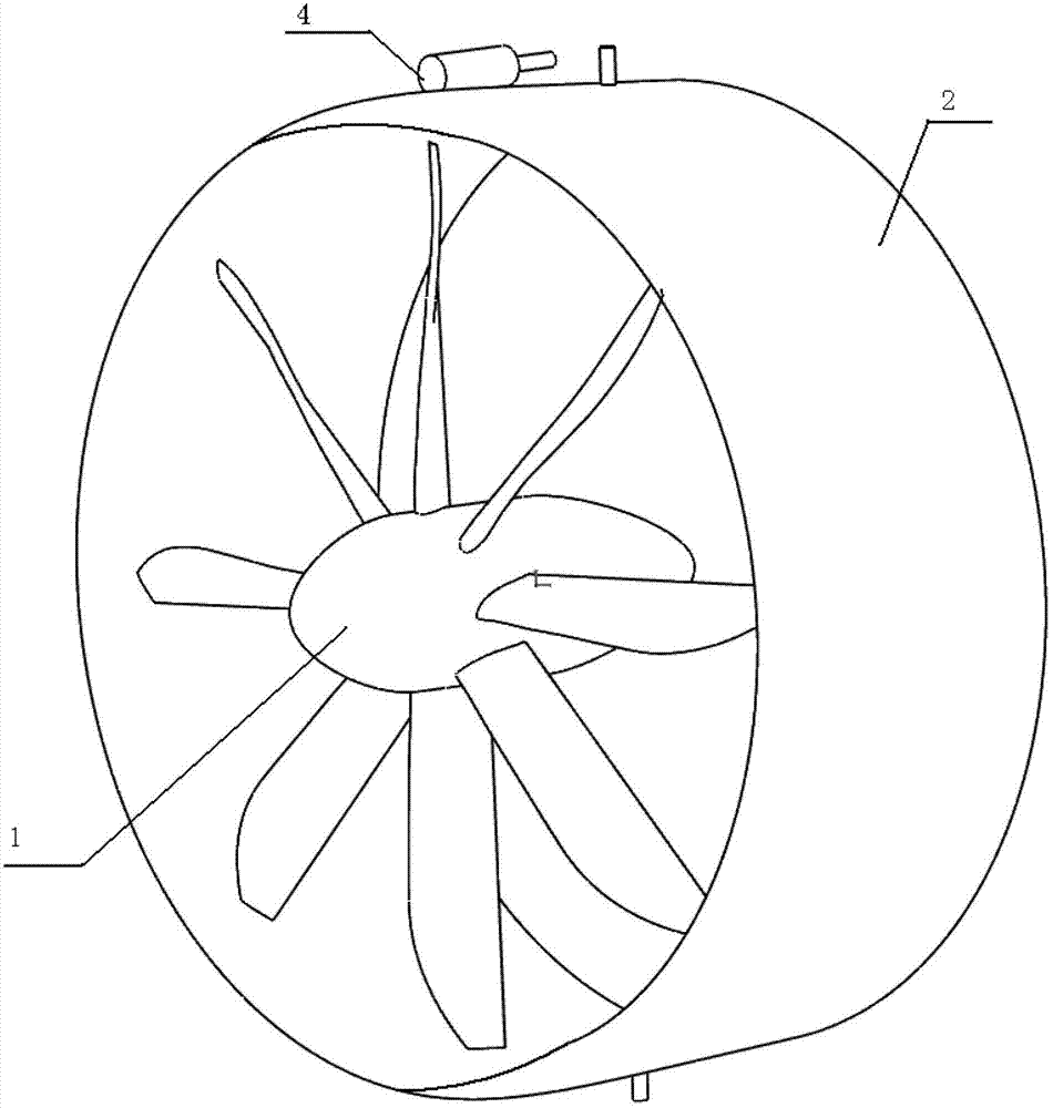
[0021] Refer to attached figure 1 And attached figure 2 , the thrust device capable of balancing the reaction torque in this embodiment includes a ducted propeller and a retractable guide cylinder 3 for changing the thrust direction.

[0022] The ducted propeller is divided into a propeller 1 that rotates to generate airflow and a duct 2 that surrounds the propeller. Two rotating shafts with a diameter of 30 mm are fixed and welded symmetrically on the outer wall of the duct shell, and the center lines of the two shafts coincide and pass through the central axis of the duct vertically. When the whole device was installed on the tail of the rotary wing aircraft, the center line of the two rotating shafts was parallel to...


PUM


Abstract

The invention discloses a thrust device capable of balancing reactive torque. The thrust device comprises a ducted propeller and a guide cylinder; two rotary shafts are symmetrically fixed on the external wall of the ducted shell of the ducted propeller; a hydraulic actuator is fixedly arranged on the side of one of the rotary shafts; the guide cylinder consists of multi-stage ring thin wall cylinders which are coaxially sleeved; actuating cylinders along the axial direction of the ring thin wall cylinders are arranged between adjacent ring thin wall cylinders; two shaft sleeves are symmetrically fixed on the internal wall of the outmost ring thin wall cylinder; the shaft sleeves are matched with the rotary shafts on the external wall of the ducted shell; and one of the rotary sleeves is laterally fixed with a swing arm; and the swing arm is matched with the hydraulic actuator. As the ducted propeller is adopted by the thrust device provided by the invention, thrust can be provided to a rotor blade airplane for flying forwards; different balanced torques can be produced through adjusting the rotary angles of the guide cylinder; as the length of the guide cylinder is adjusted, the ducted propeller and the guide cylinder can reach the best matching state at different speeds, so that higher aerodynamics efficiency can be realized.

Description

technical field [0001] The invention relates to the technical field of aerodynamics, in particular to a thrust device capable of balancing counter torque. Background technique [0002] For an aircraft that flies by generating lift through the rotation of the rotor, when the rotor rotates to generate lift, a counter torque will be generated on the fuselage. At present, there are coaxial double propellers, single rotor with tail rotor, etc., but for the rotary wing aircraft with multiple flight modes (application number is 201110213680.1), the rotor needs to be locked as a fixed wing during flight. , so the existing coaxial dual-propeller mode is not suitable for the above-mentioned rotary wing aircraft; and the tail rotor structure has a high accident rate of the tail rotor and the tail rotor drive system. When the rotorcraft is flying at low altitude or sticking to the ground, The high-speed rotating tail rotor is prone to problems such as collision with obstacles and accid...

Claims


Application Information

Patent Timeline
Patent Type & Authority Applications(China)
IPC IPC(8): B64C27/22
Inventor 高正红田力邓阳平李亮明张德虎黄江涛赵轲
Owner NORTHWESTERN POLYTECHNICAL UNIV
Why Eureka
Try Eureka