A multi-stage atomized heavy oil catalytic cracking anti-coking nozzle
A heavy oil catalysis and anti-coking technology, which is applied in catalytic cracking, cracking, petroleum industry, etc., can solve the problems of catalyst breakage, steam injection hole wear, high feed oil injection speed, etc., to suppress ejection backflow, destroy oil film accumulation, eliminate The effect of large droplets
- Summary
- Abstract
- Description
- Claims
- Application Information
AI Technical Summary
Problems solved by technology
Method used
Image
Examples
Embodiment 1
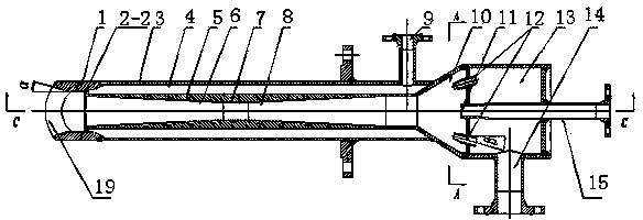
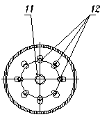
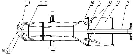
[0050] Such as figure 1 , figure 2 , image 3 and combine Figure 7 , a multi-stage atomized heavy oil catalytic cracking anti-coking nozzle, the nozzle includes an inner pipe 5, an outer pipe 3, a nozzle 1, a raw oil inlet 14 and a primary steam inlet 15; the inner pipe 5 and the outer pipe 6 The annular cavity between them constitutes the annular secondary steam chamber 4, and a secondary steam inlet 9 is arranged on the side away from the nozzle; the inner pipe 5 has a constriction section 8, a throat section 7 and a diffusion section 6, and the spray head The front end has a nozzle outlet 19; the feed oil inlet 14 communicates with the manifold chamber 13, and communicates with the frustum-shaped mixing chamber 10 through a plurality of evenly distributed feed oil nozzles 12 at a certain angle to the nozzle axis, so that When the raw oil enters the mixing chamber, it is divided into multiple fine jets. Due to the sudden drop in pressure at the raw oil nozzle 12, the ra...
Embodiment 2
[0064] Such as Figure 4 , Figure 5 , Figure 6 and combine Figure 7 , the main scheme of this embodiment is the same as that of embodiment 1. In this embodiment, the primary steam nozzle adopts the form of connecting pipe 11; and the raw material oil nozzle 12 adopts the form of direct drilling. This embodiment is suitable for the flow of raw material oil less than 5t / h At this time, the overall size of the nozzle is small, and it is difficult to weld the pipe at the inlet end of the mixing chamber 10, but at this time the thickness of the orifice plate at the inlet end of the mixing chamber is not less than 10 mm.
Embodiment 3
[0066] Such as Figure 8 , Figure 9 , Figure 10 and combine Figure 11 , the main scheme of this embodiment is the same as that of embodiment 1, and the difference between this embodiment and embodiment 1 and embodiment 2 in this embodiment is the form of the primary steam nozzle 11 and the raw material oil nozzle 12 in the mixing chamber 10 parts, and the primary steam is Introduced by the primary steam inlet 15, it first enters the primary steam distribution chamber 16, and then enters the mixing chamber 10 through the primary steam nozzle 11. There are one or more primary steam nozzles 11 arranged at the inlet end of the mixing chamber 10, and there are nine in this embodiment. (Such as Figure 9 As shown in the concentric double circle), the primary steam outlet 11 is parallel to the axis of the nozzle, and adopts the form of a connecting pipe.
[0067]After the heated raw oil enters the nozzle from the raw oil inlet 14, it first enters the manifold chamber 13 of the...
PUM
 Abstract
Description
Claims
Application Information
 - R&D
- Intellectual Property
- Life Sciences
- Materials
- Tech Scout
- Unparalleled Data Quality
- Higher Quality Content
- 60% Fewer Hallucinations
Browse by: Latest US Patents, China's latest patents, Technical Efficacy Thesaurus, Application Domain, Technology Topic, Popular Technical Reports.
© 2025 PatSnap. All rights reserved.Legal|Privacy policy|Modern Slavery Act Transparency Statement|Sitemap|About US| Contact US: help@patsnap.com


