
Node for combination beam and 45-degree arranged cross steel reinforced concrete column

A technology of concrete column and cross-shaped steel, applied in the direction of building, building structure, etc., can solve the problems of shear brittle failure, unfavorable stress state of structure, structural collapse, etc.

Inactive Publication Date: 2012-12-19
NORTH CHINA UNIV OF WATER RESOURCES & ELECTRIC POWER
View PDF5 Cites 8 Cited by
  • Summary
  • Abstract
  • Description
  • Claims
  • Application Information

AI Technical Summary

Problems solved by technology

Beam-column joints are prone to shear brittle failure. Once the joints are damaged, the structure will be in an extremely unfavorable stress state, and even lead to the collapse of the entire structure.

Method used


Image

  • Node for combination beam and 45-degree arranged cross steel reinforced concrete column
  • Node for combination beam and 45-degree arranged cross steel reinforced concrete column
  • Node for combination beam and 45-degree arranged cross steel reinforced concrete column

Examples


Embodiment Construction

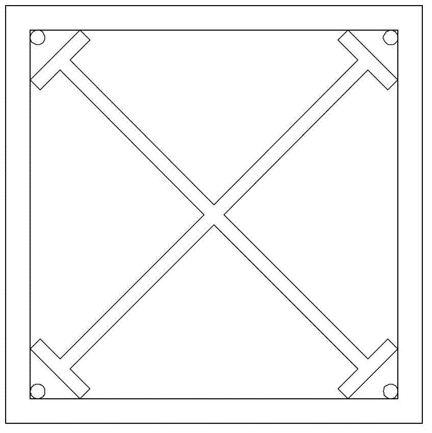
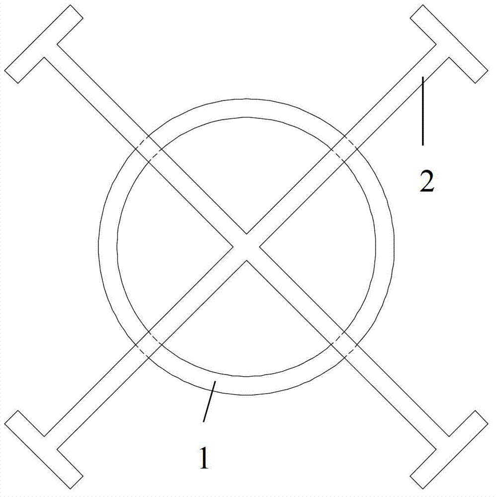
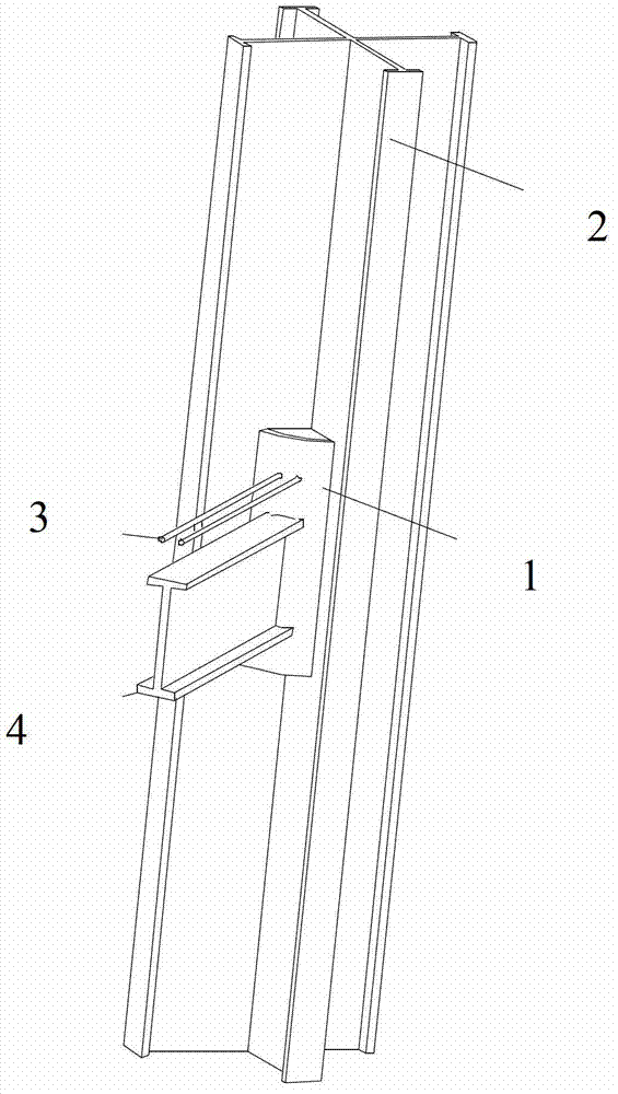
[0036] The shaped steel column 1 is made by a professional steel structure company, and the shaped steel column 1 is welded by I-shaped steel 5 and two T-shaped steels 7 . When making the I-beam 5, cut out a cavity 6 within the range of node height, the hole height of the cavity 6 is equal to the height of the round steel pipe, and the hole width is the outer diameter of the round steel pipe. The round steel pipe 1 is placed on the I-beam 5 In the cut cavity 6, the webs of the round steel pipe 1 and the I-beam 5 are welded. The two T-shaped steels 7 are welded to the I-shaped steel 5, and the round steel pipe 1 is welded to the webs of the two T-shaped steels 7 at the same time. After the above work is completed, you can see as follows figure 2 shown. The steel bar 3 in the composite beam is plug-welded on the round steel pipe 1, and the steel beam 4 in the composite beam is welded on the round steel pipe 1. The stirrups of the nodes can be welded to the webs of the steel ...


PUM


Abstract

A node for a combination beam and a 45-degree arranged cross steel reinforced concrete column relates to a steel reinforced concrete structure, and is used for overcoming the defects of the prior art and solving the problem of the rigid connection of the combination beam and the 45-degree arranged cross steel reinforced concrete column with a flange in a project. A circular steel tube is arranged within the height scope of a steel column internal node, so the connection problem of the rigid connection of the combination beam and the 45-degree arranged cross steel reinforced concrete column with the flange is solved. The external diameter of the circular steel tube is 40%-60% of the side length of a square column, the wall thickness of the circular steel tube is larger than or equal to the thickness of the flange edge of a steel beam in the combination beam, moreover, the wall thickness of the steel beam is not less than a half of the diameter of the maximum longitudinal bar of the combination beam, and the height of the circular steel tube needs to be respectively higher than the external longitudinal bars of the combination beam and the lower flange edge of the steel beam by 100 millimeters. The circular steel tube and a steel web in the column are welded through fillet welding, the steel beam in the combination beam is welded on the circular steel tube, the longitudinal bars of the combination beam are in plug welding on the circular steel tube, and the hopping of the node is welded on a steel beam web. The node disclosed by the invention is used for the steel reinforced concrete structure.

Description

technical field [0001] The invention relates to a composite beam and steel concrete column joint, which belongs to the steel concrete structure. Background technique [0002] Shaped steel concrete column refers to the structure in which shaped steel is arranged in concrete, and it is equipped with certain transverse stirrups and longitudinal reinforcement bars. Steel concrete columns have the advantages of high bearing capacity, high rigidity and good seismic performance, and have been widely used in long-span structures and high-rise buildings in earthquake zones. [0003] The 45-degree cross-shaped steel concrete column with flange is arranged on the diagonal line of the column with cross-shaped steel with flange. Resist multi-dimensional earthquake action; the area and strength of the concrete constrained by the steel in this type of steel concrete column are much higher than that of ordinary steel concrete columns, so the ductility and energy dissipation capacity of the...

Claims


Application Information

Patent Timeline
IPC IPC(8): E04B1/58
Inventor 管俊峰张建伟白卫峰郝颖姚贤华张翌娜
Owner NORTH CHINA UNIV OF WATER RESOURCES & ELECTRIC POWER
Learn More