Transmission mechanism of rotational moulding machine

A technology of transmission mechanism and rotomolding machine, applied in the direction of transmission device, mechanical equipment, belt/chain/gear, etc., can solve problems such as wear, chain length elongation, chain elongation, etc., to reduce noise, prevent deformation, improve The effect of stability

Inactive Publication Date: 2012-12-19
华瑞传动科技南通有限公司
View PDF5 Cites 2 Cited by
  • Summary
  • Abstract
  • Description
  • Claims
  • Application Information

AI Technical Summary

Problems solved by technology

The transmission mechanism of the rotomolding machine with this structure will wear out after a long time of use, resulting in the length of the chain being elongated, and the elongated chain will emit extra noise during the transmission process.
Because the volume of the rotational molding machine is huge, the chain is also very long, so the phenomenon of the chain being stretched will be more obvious
At the same time, only one chain is usually set in the transmission mechanism of the rotomolding machine in the prior art. Once it is tempered, the two driven shafts will stop rotating, which will seriously affect the working efficiency of the rotomolding machine.

Method used


Image

  • Transmission mechanism of rotational moulding machine

Examples


Embodiment Construction

[0019] The present invention will be described in detail below in conjunction with the implementations shown in the drawings, but it should be noted that these implementations are not limitations of the present invention, and those of ordinary skill in the art based on the functions, methods, or structural changes made by these implementations Equivalent transformations or substitutions all fall within the protection scope of the present invention.

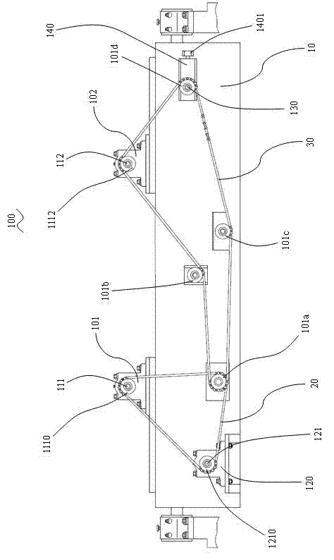
[0020] Please refer to figure 1 as shown, figure 1 It is a front view of a specific embodiment of a transmission mechanism of a rotational molding machine in the present invention. In this embodiment, a transmission mechanism 100 of a rotational molding machine includes:

[0021] The base 10 , and the two first bearing seats 101 , 102 disposed above the base 10 , each first bearing seat 101 , 102 accommodates a driven shaft 111 , 112 . Specifically, driven wheels 1110 , 1112 are provided at the ends of the driven shafts 111 , 1...


PUM


Abstract

The invention provides a transmission mechanism of a rotational moulding machine. The transmission mechanism comprises a base, two first bearing blocks, four tensioning wheels, a second bearing block, a first transmission part and a second transmission part. The two first bearing blocks are arranged above the base. Driven shafts are contained in the first bearing blocks, and driven wheels are arranged at the tail ends of the driven shafts. The four tensioning wheels are arranged on the side of the base. A drive shaft is contained in the second bearing block, and a drive wheel is arranged at the tail end of the drive shaft. The first transmission part is wound on the drive wheel, the driven wheel and one tensioning wheel. The second transmission part and the first transmission part share the tensioning wheel and are wound on the other three tensioning wheels and the driven wheels. The transmission parts are designed as two independent structures and are abutted to the four tensioning wheels mutually, so that deformation of the transmission parts is prevented, and noise is lowered. The transmission parts in fine deformation can be adjusted in terms of position by an adjusting bolt arranged on a boss, and accordingly the transmission parts can be reliably wound on the drive wheel, the driven wheels and the tensioning wheels, and stability of the transmission mechanism of the rotational moulding machine is increased.

Description

technical field [0001] The invention relates to a transmission mechanism, in particular to a transmission mechanism of a rotational molding machine. Background technique [0002] Rotational molding is a process method for forming large hollow storage tanks. Rotational molding is to add resin powder into the rotational molding mold, then heat the rotational molding mold and make it rotate continuously along two parallel axes, the resin in the rotational molding mold is gradually and evenly coated and melted under the action of gravity and heat Adhere to the inner surface of the rotational molding mold to form the desired shape of the storage tank, then cool the mold and demould to obtain the storage tank. [0003] At present, large-scale hollow storage tanks are generally manufactured through a rotational molding process on a rotational molding machine. Due to the huge size and weight of the rotomolding machine, it is usually more than ten meters or even tens of meters ...

Claims


Application Information

Patent Timeline
Patent Type & Authority Applications(China)
IPC IPC(8): F16H7/06F16H7/02F16H7/08B29C41/34B29C41/04
Inventor 张洪昌
Owner 华瑞传动科技南通有限公司
Why Eureka
Try Eureka