Heat resistance-free heat pipe heating furnace and heating method thereof

A technology of heating furnace and heat pipe heat exchanger, which is applied to heat storage heaters, fluid heaters, lighting and heating equipment, etc. The heat exchange effect of the heat exchange system and other issues can achieve the effects of green environmental protection, social and economic benefits, increase the heat transfer rate of the phase change, and have a significant energy saving effect.

Inactive Publication Date: 2012-12-19
王凯一
View PDF8 Cites 4 Cited by
  • Summary
  • Abstract
  • Description
  • Claims
  • Application Information

AI Technical Summary

Problems solved by technology

[0003] 1. Since the high-temperature steam is heated from the lower part of the heat exchange tube, the water film on the heat exchange surface is thicker, which reduces the heat exchange efficiency;
[0004] 2. Due to the use of ordinary steam heat exchange, there is a large amount of air in the heat exchange space, and the existence of relatively non-conductive air reduces the heat exchange effect of the heat exchanger;
[0005] 3. The presence of air reduces the pressure change during phase change heat, directly affects the vaporization speed of the heat medium in the heater, and reduces the heat absorption capacity of the heater;
[0006] 4. Because the heat transfer and condensation are in the same space, it causes a large thermal resistance and reduces the heat exchange effect of the entire heat exchange system;
[0007] 5. The use of heat pipe technology only stays in the form of tubular heat pipes. Due to the limitation of the use of tubular heat pipe structure, the application of heat pipe technology is greatly reduced.

Method used


Image

  • Heat resistance-free heat pipe heating furnace and heating method thereof
  • Heat resistance-free heat pipe heating furnace and heating method thereof

Examples


Embodiment approach

[0045] Its normal operation implementation method includes the following steps:

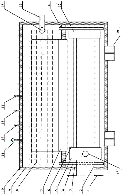
[0046]1. After the installation and connection of the non-resistance heat pipe heating furnace and the process of the heated medium are completed, it must be checked to ensure that the heated medium and the gas source process of the non-resistance heat pipe heating furnace are correct. Then, the non-resistance heat pipe heating furnace is evacuated, and the pressure in the cavity is required to be ≤-0.07.

[0047] 2. When the non-resistance heat pipe heating furnace achieves the required vacuum degree, the burner can be ignited, the gas volume can be controlled by the gas volume control valve, and the chimney suction can be controlled by the chimney seat to make the gas burn fully. After fifteen minutes, turn the flow on gradually. After about 30 minutes, use a thermometer to detect the temperature of the heated medium outlet of the heating furnace, and adjust the gas volume to reach the require...


PUM


Abstract

The invention relates to a heat resistance-free heat pipe heating furnace and a heating method thereof. The heat resistance-free heat pipe heating furnace comprises a heat pipe medium steam generator, a beam current device, a medium liquid reflux pipe, a heat pipe heat exchanger, a heat insulation layer and a chimney, wherein the bottom of the beam current device is connected to the heat pipe medium steam generator and the top of the beam current device is connected to the heat pipe heat exchanger so that high-temperature steam generated by the heat pipe medium steam generator is directly lifted to the top of a cavity of the heat pipe heat exchanger to form a heat exchange state of high-temperature medium steam scouring a heat exchanging coil pipe from top to bottom; the upper end of the medium liquid reflux pipe is communicated with the heat pipe heat exchanger, and the lower end of the medium liquid reflux pipe is connected with the cavity of the heat pipe medium steam generator so that condensed medium liquid is directly reflux ed to the heat pipe medium steam generator. In the invention, the medium liquid is positioned on respectively independent channels from heated vaporization to phase-change heat transfer to condensing reflux so that the heat resistance loss of heating power shear, which is caused in such a way that the high-temperature medium steam and condensed liquid of the traditional heat pipe are positioned in a same flow channel, is eliminated, and therefore, the energy-saving effect is outstanding.

Description

technical field [0001] The invention relates to a heat pipe heating device and process in the petrochemical industry, in particular to a heat pipe heating furnace without heat resistance and a heating method. Background technique [0002] At present, in the production of my country's petrochemical industry, most of the various heating furnaces used adopt traditional and conventional heating furnace structures and heating process principles, resulting in the following low-efficiency heat transfer problems: [0003] 1. Since the high-temperature steam is heated from the lower part of the heat exchange tube, the water film on the heat exchange surface is thicker, which reduces the heat exchange efficiency; [0004] 2. Due to the use of ordinary steam heat exchange, there is a large amount of air in the heat exchange space, and the existence of relatively non-conductive air reduces the heat exchange effect of the heat exchanger; [0005] 3. The presence of air reduces the p...

Claims


Application Information

Patent Timeline
Patent Type & Authority Applications(China)
IPC IPC(8): F24H7/02F24H9/00
Inventor 王凯一王为旭刘飞龙赵年合
Owner 王凯一
Why Eureka
Try Eureka