Auxiliary equipment for continuous casting solidification structure image scanning and application method thereof

A technology of solidification structure, imaging and scanning, which is applied in the preparation of test samples, measuring devices, and material analysis through optical means, etc. It can solve the problem of not being able to meet the inspection of metallographic dendrite structure, and not applicable to the original heavy sample of cast slab with 3 degrees of freedom 180-degree rotation and other problems in motion, to achieve the effect of improving scanning imaging efficiency, compact structure, and convenient operation

Active Publication Date: 2015-03-11
ANGANG STEEL CO LTD
View PDF2 Cites 0 Cited by
  • Summary
  • Abstract
  • Description
  • Claims
  • Application Information

AI Technical Summary

Problems solved by technology

[0003] In the prior art, the stage or carrier of experimental instruments such as microscopes and hardness testers can only be clamped, fixed, translated and lifted under the condition of bearing a weight of tens of grams, or can only be clamped, fixed, translated and lifted in a horizontal plane around a vertical axis. The rotating sample cannot be applied to the 3-degree-of-freedom movement and 180-degree rotation along the horizontal plane of the original heavy sample of the cast slab in large-scale industrial production. and metallographic dendrite examination

Method used


Image

  • Auxiliary equipment for continuous casting solidification structure image scanning and application method thereof
  • Auxiliary equipment for continuous casting solidification structure image scanning and application method thereof
  • Auxiliary equipment for continuous casting solidification structure image scanning and application method thereof

Examples


Embodiment Construction

[0016] The present invention will be further described below with reference to the accompanying drawings.

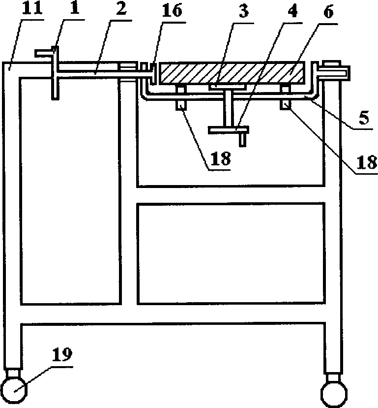
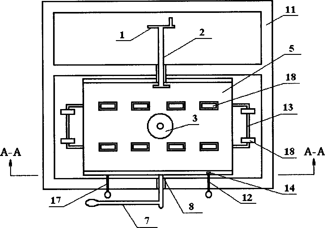
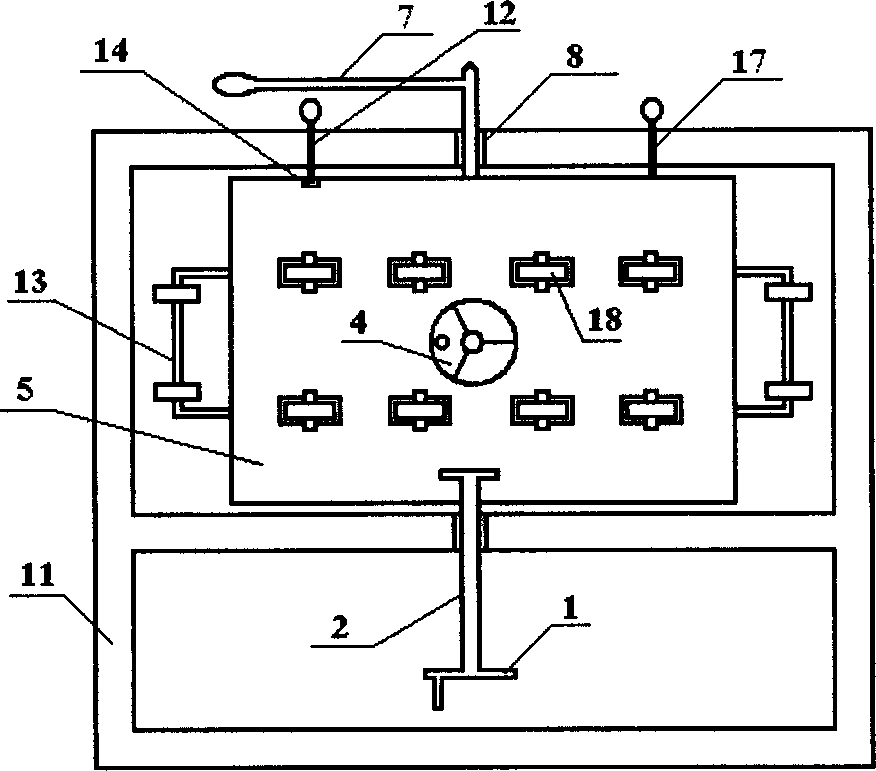
[0017] It is not difficult to see from the accompanying drawings that the auxiliary equipment for imaging and scanning of the solidified structure of the continuous casting slab consists of two parts: a sample turning device and a scanner lifting device. The sample inverting device is mainly composed of a bracket 11 and a sample bracket 5 . Described support 11 is square, and available metal pipe is done, and a universal wheel 19 is respectively installed on the four pins of its lower end, can move toward arbitrary direction. The sample bracket 5 is U-shaped, and each side is connected to the upper frame of the bracket 11 through a bushing 8 . A fastening screw 2 is worn in the shaft sleeve 8 inside the sample bracket 5, one end of the fastening screw 2 is provided with a fastening handle wheel 1, and the other end is provided with a fastening disc 16, and the rotating ...


PUM


Abstract

The invention provides auxiliary equipment for continuous casting solidification structure image scanning and an application method thereof. The equipment comprises a sample turning device and a scanner lifting device. The sample turning device is composed of a support and a sample bracket. The bracket is connected inside the upper frame of the support through a spindle sleeve. A fastening leading screw is threaded through a spindle sleeve at the inner side. A turning rod is threaded through a spindle sleeve at the outer side. A locking pin is installed on the support and fits with a location hole. The scanner lifting device is composed of a lifting platform, a lifting leading screw and a scanner bracket. A cantilever type scanner bracket is installed on the lifting leading screw. The application method comprises the following steps of: placing a sample; adjusting the height; clamping and turning the sample; moving the turning device to make an etched surface of the sample face a scanning panel; turning the sample bracket after scanning, loosing and taking out the sample. The auxiliary equipment provided by the invention has a compact and reasonable structure, is suitable for large-scale casting samples, can move in the three degrees of freedom in a space and rotate 180 degrees along the horizontal axis, requires no power source, is convenient to operate, can be used to accurately position, and is safe and reliable.

Description

technical field [0001] The invention belongs to equipment for imaging and scanning, in particular to an auxiliary equipment for continuous casting slab flipping motion imaging and scanning and a using method thereof. Background technique [0002] In the past conventional metal solidification structure inspection, most of them were limited to the small sample structure inspection of dozens of grams to hundreds of grams in cast and rolled states. With the successful development of metallographic dendrite inspection technology of solidified structure and the development of computer scanning technology, digital scanning imaging technology has been gradually introduced into modern metallographic and metallurgical inspection work. Scanning and imaging inspections of hundreds of kilograms of billet samples produced in large-scale industries have begun. Due to the high resolution of scanning imaging and through photoelectric conversion and image quality optimization, dendrites and l...

Claims


Application Information

Patent Timeline
Patent Type & Authority Patents(China)
IPC IPC(8): G01N21/01G01N1/36
Inventor 隋晓红李平张鹏远赵宝存苏洪英
Owner ANGANG STEEL CO LTD
Why Eureka
Try Eureka