
Dynamic scan driving method for smectic phase LCD (liquid crystal display)

A liquid crystal display and driving method technology, applied to static indicators, instruments, etc., can solve the problems of aggravated cumulative effect of swiping the screen and waste of electric energy, etc., and achieve the effects of reducing power consumption, reducing the cumulative effect of swiping the screen, and prolonging the service life

Active Publication Date: 2012-12-19
HALATION PHOTONICS CORP
View PDF5 Cites 12 Cited by
  • Summary
  • Abstract
  • Description
  • Claims
  • Application Information

AI Technical Summary

Problems solved by technology

[0005] However, since the values ​​of the voltage waveforms on the row and column electrodes of the current smectic liquid crystal display are fixed, that is, they are all high-frequency high-voltage positive and negative pulses with a voltage amplitude of Umx. Therefore, it can be seen that the voltage amplitude used If the fixed high-frequency high-voltage positive and negative pulses drive the display screen, it will inevitably cause a serious waste of electric energy, and will aggravate the cumulative effect of swiping the screen

Method used


Image

  • Dynamic scan driving method for smectic phase LCD (liquid crystal display)
  • Dynamic scan driving method for smectic phase LCD (liquid crystal display)
  • Dynamic scan driving method for smectic phase LCD (liquid crystal display)

Examples


Embodiment Construction

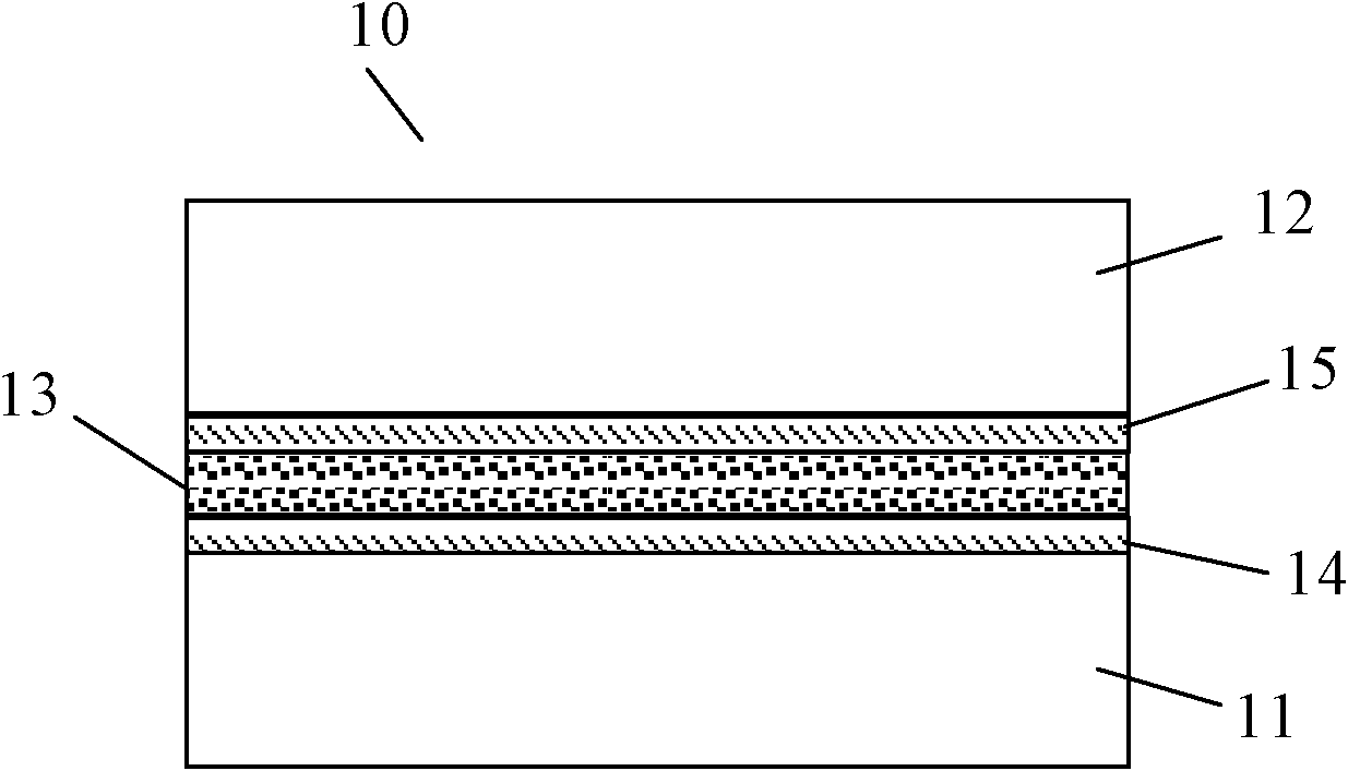
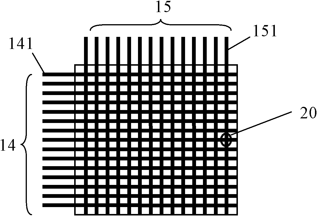
[0022] The dynamic scanning driving method of the smectic phase liquid crystal display screen of the present invention is a method for the smectic phase liquid crystal display screen. Such as figure 2 and image 3 As shown, the smectic liquid crystal display screen 10 includes a first base layer 11 and a second base layer 12, and the material of the first base layer 11 and the second base layer 12 can be transparent glass or plastic. Between the first base layer 11 and the second base layer 12, there is a mixed layer 13 formed by mixing smectic liquid crystals and additives. The smectic liquid crystals (also known as smectic liquid crystals, microscopically shown as smectic liquid crystal molecules, see below) are compounds with siloxy groups, tetracyanotetraoctylbiphenyl or tetradecyl tetraacetate Any one or any mixture of cyanobiphenyls. The additives are compounds with conductive properties, such as hexadecyltriethylammonium bromide and other compounds containing conduc...


PUM


Abstract

The invention discloses a dynamic scan driving method for a smectic phase LCD (liquid crystal display). The method comprises the following steps of: scanning and driving all lines of a display screen; applying a corresponding line pulse to the scanned and driven line when each line is scanned and driven, wherein the line pulse is a high-frequency high-voltage positive and negative pulse with a duty ratio of 50%; applying zero-volt voltages to other lines free from scanning and driving; and meanwhile, applying a corresponding column pulse to each column, wherein voltage amplitudes of the line pulse applied on each line and the column pulse applied on each column can be controlled according to amount of required voltage energy caused by each display state on pixels, different distances of leading-out terminals of line distance column electrode and the different distances of the leading-out terminals of column distance line electrode. According to the dynamic scan driving method disclosed by the invention, the voltage amplitudes of the line pulse and the column pulse can be dynamically adjusted in the whole scanning and driving period, therefore, a phenomenon that the pixels with no need of being driven by high-voltage energy are driven by excessively high voltage energy can be avoided to a great degree, and power consumption is dramatically reduced.

Description

technical field [0001] The invention relates to a scanning driving method of a display screen, in particular to a dynamic scanning driving method of a smectic phase liquid crystal display screen. Background technique [0002] At present, smectic liquid crystal display screens (also known as smectic liquid crystal display screens) generally use high-frequency high-voltage positive and negative pulses as voltage waveforms for driving row and column electrodes, such as figure 1 As shown, the high-frequency high-voltage positive and negative pulses are a waveform form realized by positive and negative pulse pairs composed of positive pulses and negative pulses. The positive pulses and negative pulses in the high-frequency high-voltage positive and negative pulses are mutually symmetrical, and the voltage amplitudes are equal, and is Umx, and the voltage amplitude Umx of the high-frequency high-voltage positive and negative pulses is constant throughout the scanning driving cycle...

Claims


Application Information

Patent Timeline
IPC IPC(8): G09G3/36
Inventor 夏兴隆孙刚王欢欢
Owner HALATION PHOTONICS CORP
Learn More