Light emitting device and illumination apparatus including same

一种发光装置、固态发光的技术,应用在照明和加热设备、照明装置的零部件、用于改变发射光的光谱特性的光学元件等方向

Inactive Publication Date: 2012-12-19
PANASONIC CORP
View PDF4 Cites 4 Cited by
  • Summary
  • Abstract
  • Description
  • Claims
  • Application Information

AI Technical Summary

Problems solved by technology

[0011] However, it should be considered that the LED light source disclosed in JP2011-060967A causes watering due to the possibility that light emitted from one LED element propagates through the first phosphor layer covering the corresponding LED element and the second phosphor layer covering the other LED element. same problem in case

Method used


Image

  • Light emitting device and illumination apparatus including same
  • Light emitting device and illumination apparatus including same
  • Light emitting device and illumination apparatus including same

Examples


Embodiment Construction

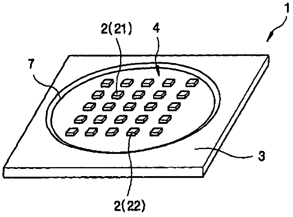
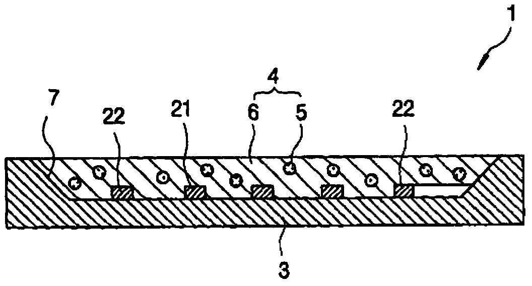
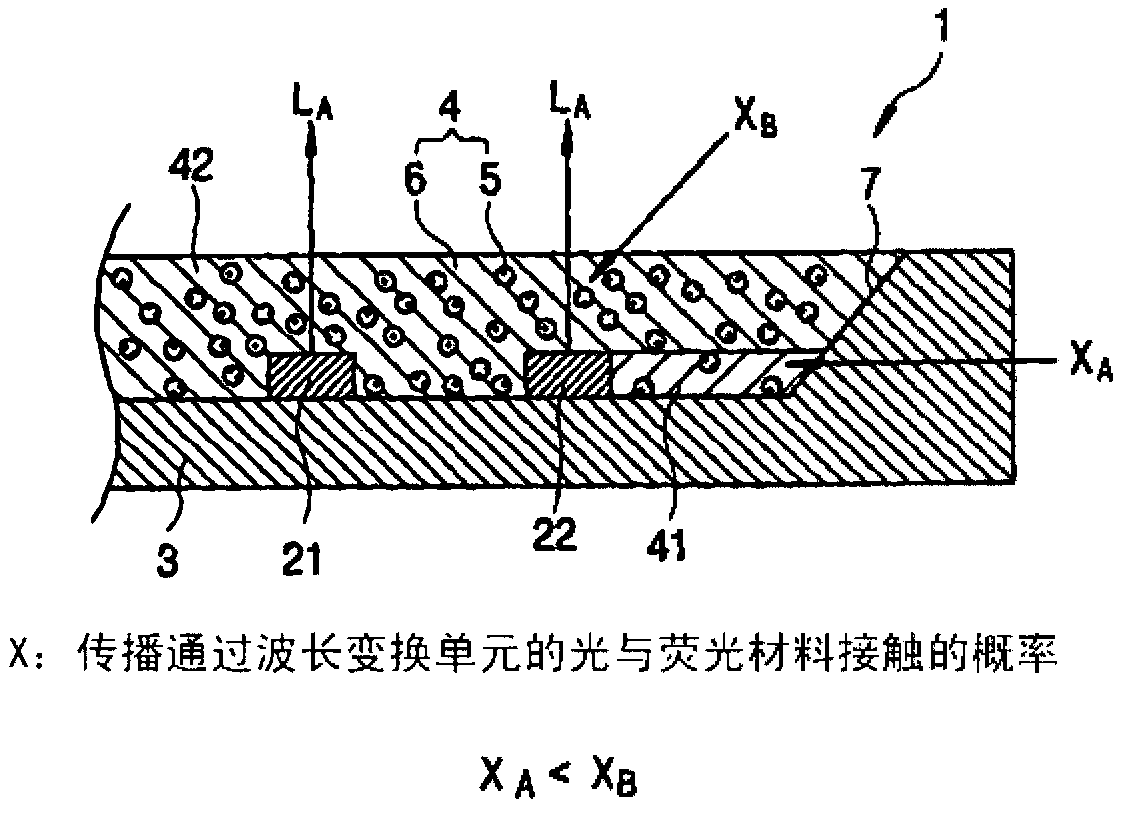
[0030] Reference will now be made to the Figures 1A to 1C A light emitting device according to a first embodiment of the present invention will be described. The light-emitting device 1 includes a plurality of solid-state light-emitting elements 2, a substrate 3 on which the solid-state light-emitting elements 2 are mounted, and a wavelength conversion unit 4 covering the solid-state light-emitting elements 2, although in Figure 1A The solid state light emitting elements 2 are shown as being arranged in the form of a 5×5 matrix in , but the present invention is not limited thereto. The wavelength conversion unit 4 includes a fluorescent material 5 (for example, a yellow fluorescent material, etc.) for converting the wavelength of blue light emitted from, for example, a blue LED, and a binder 6 holding the fluorescent material 5 .

[0031] A circular recess 7 is formed on the surface of the substrate 3 and a wiring pattern (not shown) is formed on the bottom of the recess 7 ...


PUM


Abstract

A light emitting device includes a plurality of solid-state light emitting elements mounted on a substrate, and a wavelength converting unit covering the solid-state light emitting elements, the wavelength converting unit containing fluorescent materials. The solid-state light emitting elements include inner solid-state light emitting elements arranged in a central position of the substrate and outer solid-state light emitting elements arranged outwardly of the inner solid-state light emitting elements, and the wavelength converting unit is configured such that a probability that light propagating through the wavelength converting unit is brought into contact with the fluorescent materials in a portion of the wavelength converting unit covering the outer solid-state light emitting elements is lower than a probability that light propagating through the wavelength converting unit is brought into contact with the fluorescent materials in other portions.

Description

technical field [0001] The present invention relates to a light-emitting device in which a solid-state light-emitting element is mounted on a substrate, and a lighting device including the light-emitting device. Background technique [0002] Conventionally, light sources such as incandescent lamps, fluorescent lamps, high-pressure discharge lamps, etc. have been used for lighting equipment. In recent years, light-emitting diode (LED) light sources have been widely used due to their low power consumption and high durability. Since one LED element emits low luminous flux, an LED light source uses a plurality of LED elements to obtain substantially the same luminous flux as a conventional light source. There is a tendency to mount LED components as compactly as possible on a substrate in order to realize high power LED light sources. [0003] An example of such an LED light source may include mixing blue and yellow light by coating a substrate LED element with a resin layer f...

Claims


Application Information

Patent Timeline
Patent Type & Authority Applications(China)
IPC IPC(8): H01L25/075H01L33/48H01L33/50F21V9/10F21Y101/02F21V9/40
CPCH01L33/508H01L25/0753H01L2924/09701H01L2924/0002H01L2924/00
Inventor 竹井尚子西冈浩二
Owner PANASONIC CORP
Why Eureka
Try Eureka