

Luminescent color conversion member and light emitting device
a technology of light-emitting devices and color conversion members, which is applied in the direction of luminescent compositions, semiconductor devices for light sources, lighting and heating apparatus, etc., can solve the problems of difficult to separate the impurities mixed in glass powder, difficult to obtain uniform chromaticity distribution, and deterioration of the components of the light-emitting device, so as to reduce the efficiency of luminescent color conversion, efficiently dissipate the heat generated by the phospho
- Summary
- Abstract
- Description
- Claims
- Application Information
AI Technical Summary
Benefits of technology
Problems solved by technology
Method used
Image

Examples
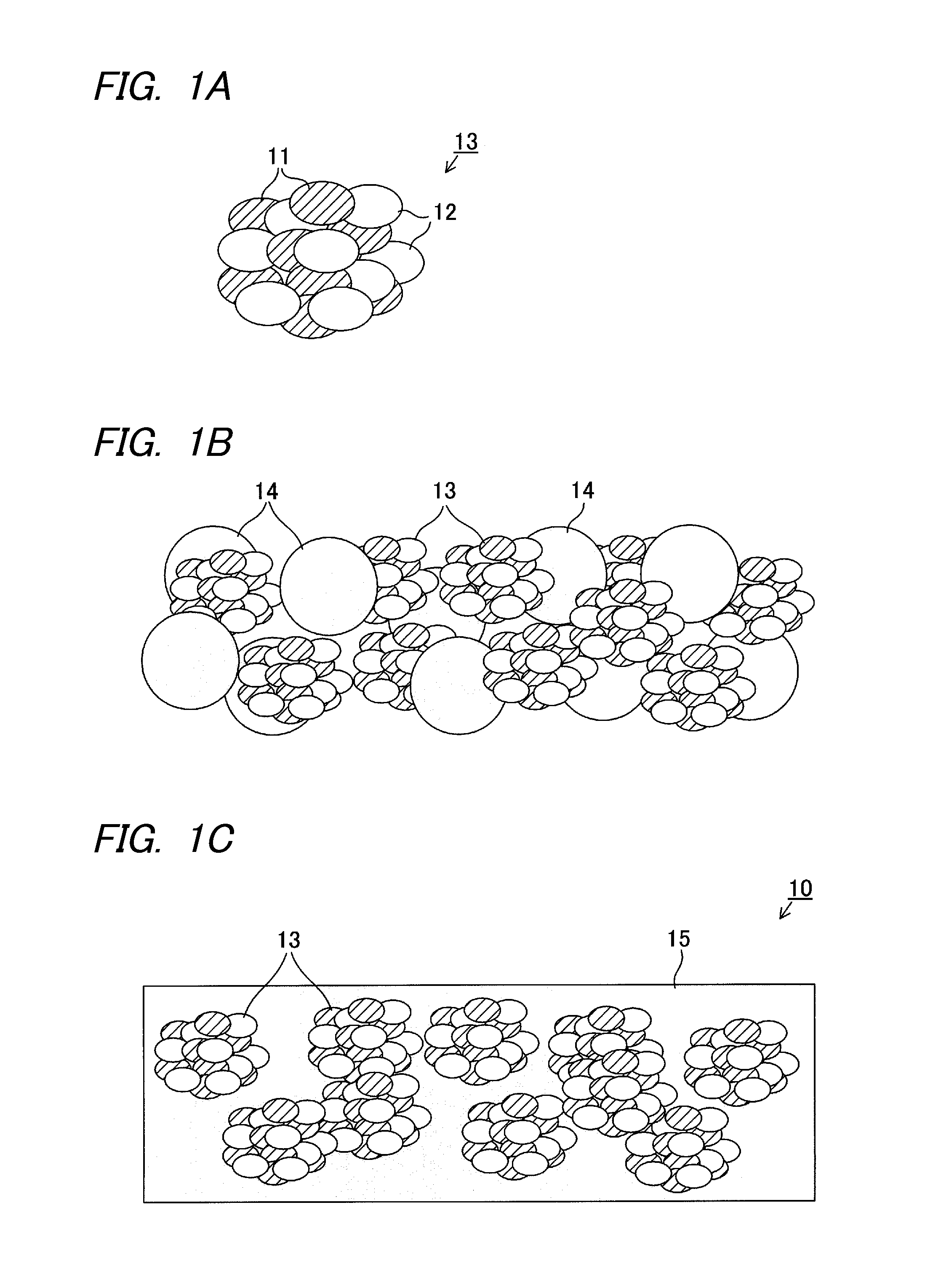
first embodiment
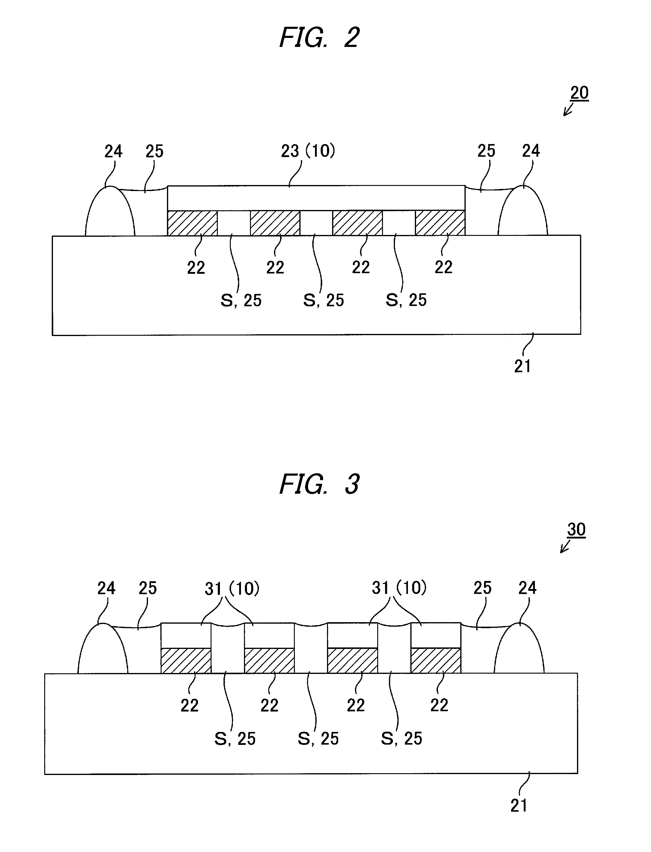
[0041]Light Emitting Device 20—First Embodiment
[0042]As shown in FIG. 2, the light emitting device 20 of the first embodiment includes an insulating substrate 21, a light emitting diode (LED) chip 22, a phosphor plate 23 (the luminescent color conversion member 10), a frame 24, a reflective layer 25 and the like.
[0043]For example, the insulating substrate (mounting board) 21 is formed by a substrate made of a bulk material of an insulating material (e.g., ceramic material such as aluminum nitride, synthetic resin material and the like) or a substrate where an insulating layer is provided on a surface of a metallic material (e.g., aluminum alloy, pure copper, copper-based alloy and the like).
[0044]Four LED chips 22 are blue LEDs having a substantially rectangular parallelepiped shape and arranged in a row with a gap S therebetween. Bottom surfaces of each LED chip 22 are electrically connected and fixedly bonded to a wiring layer (not shown) formed on the surface of the insulating su...
second embodiment
[0052]Light Emitting Device 30—Second Embodiment
[0053]As shown in FIG. 3, the light emitting device 30 of the second embodiment includes the insulating substrate 21, the LED chip 22, a phosphor plate 31 (the luminescent color conversion member 10), the frame 24, the reflective layer 25 and the like. The light emitting device 30 of the second embodiment is different from the light emitting device 20 of the first embodiment in that one phosphor plate 23 is replaced by four phosphor plates 31.
[0054]Each phosphor plate 31 is obtained by forming the luminescent color conversion member 10 into a flat plate. The size and shape of each phosphor plate 31 seen in a plan view are substantially the same as the size and shape of the upper surfaces of each LED chip 22 seen in a plan view. Each phosphor plate 31 is, respectively, fixedly attached to the upper surfaces of each LED chip 22 so as to cover the upper surfaces of each LED chip 22. Similarly to the phosphor plate 23 of the first embodime...
third embodiment
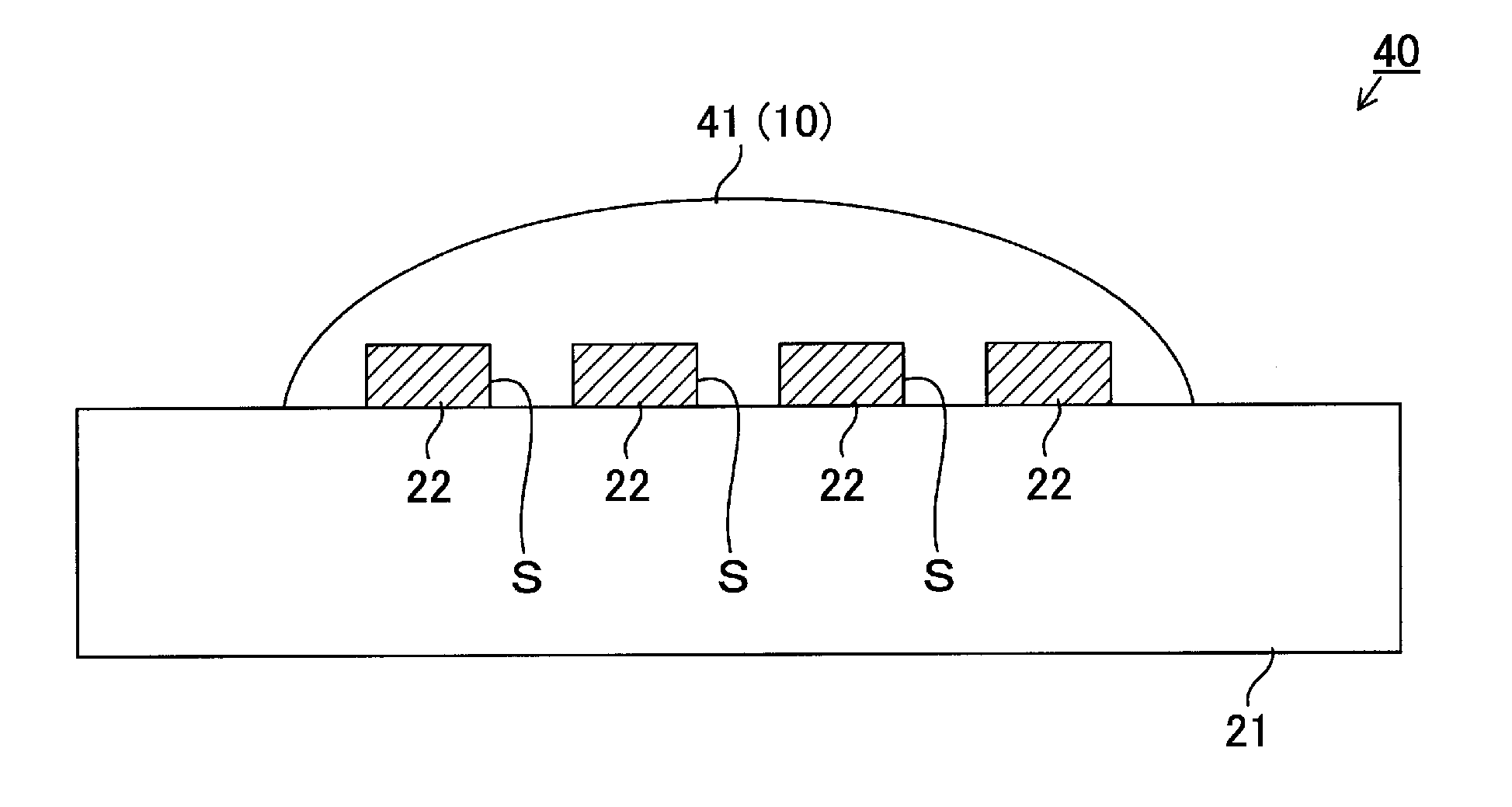
[0057]Light Emitting Device 40—Third Embodiment
[0058]As shown in FIG. 4B, the light emitting device 40 of the third embodiment includes the insulating substrate 21, the LED chip 22, a phosphor layer 41 (the luminescent color conversion member 10) and the like. The light emitting device 40 of the third embodiment is different from the light emitting device 20 of the first embodiment in that the frame 24 and the reflective layer 25 are omitted and the phosphor plate 23 is replaced by the phosphor layer 41.
[0059]As shown in FIG. 4A, the luminescent color conversion member 10 formed into a flat plate is opposed to each LED chip mounted on the insulating substrate 21 and a press working is performed while heating the luminescent color conversion member 10. In this way, the upper surfaces and side surfaces of each LED chip 22 are covered by the phosphor layer 41 which is made of the luminescent color conversion member 10 heated and softened. At this time, the luminescent color conversion ...
PUM
| Property | Measurement | Unit |
|---|---|---|
| particle size | aaaaa | aaaaa |
| particle size | aaaaa | aaaaa |
| particle size | aaaaa | aaaaa |
Abstract
Description
Claims
Application Information