
Diffuse type fine grid line cell

A grid-line cell and diffusion-type technology, applied in the field of solar cells, can solve the problems of increasing manufacturing cost, small power loss, and increasing the amount of slurry used, and achieve the effects of improving electrical performance efficiency, small power loss, and increasing collection volume.

Inactive Publication Date: 2012-12-19
ZNSHINE PV TECH
View PDF0 Cites 0 Cited by
  • Summary
  • Abstract
  • Description
  • Claims
  • Application Information

AI Technical Summary

Problems solved by technology

[0002] At present, in the industrialization technology of crystalline silicon solar cells, solar cells have the highest conversion efficiency and the most mature technology. However, compared with conventional energy sources, lower power generation efficiency and relatively higher cost restrict its development. Among the factors affecting efficiency The grid line of the cell is one of the key factors. The grid line design of the light-receiving surface of the solar cell is to collect the photocurrent to the maximum, that is, the grid line should be denser and thicker, the better, but this will inevitably reduce the light-receiving surface of the silicon cell. A well-designed grid line structure will minimize the series resistance of the battery, thereby minimizing power loss and maximizing output power. So far, when designing the grid line, it is necessary to make the grid line a very high and narrow cross-sectional area to reduce Series resistance, which increases the amount of paste used and greatly increases the manufacturing cost

Method used


Image

  • Diffuse type fine grid line cell
  • Diffuse type fine grid line cell

Examples


Embodiment Construction

[0014] The present invention is described in further detail now in conjunction with accompanying drawing. These drawings are all simplified schematic diagrams, which only illustrate the basic structure of the present invention in a schematic manner, so they only show the configurations related to the present invention.

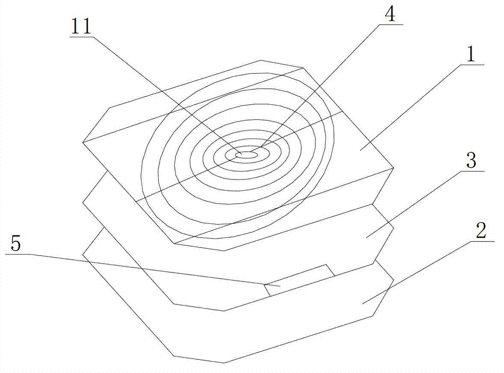
[0015] like figure 1 The diffused fine-grid battery shown includes a cell body 1, the four corners of the cell body 1 are chamfered, and an insulating film 3 and a conductive film 2 are sequentially pasted on the back of the cell body 1, and the back electrode 5 is insulated The film 3 is isolated from the conductive film 2, and the front grid line 4 is provided on the front of the battery sheet 1, and a central hole 11 is opened in the center of the battery sheet 1, and the front grid line 4 is connected to the back electrode 5 through the center hole 11.

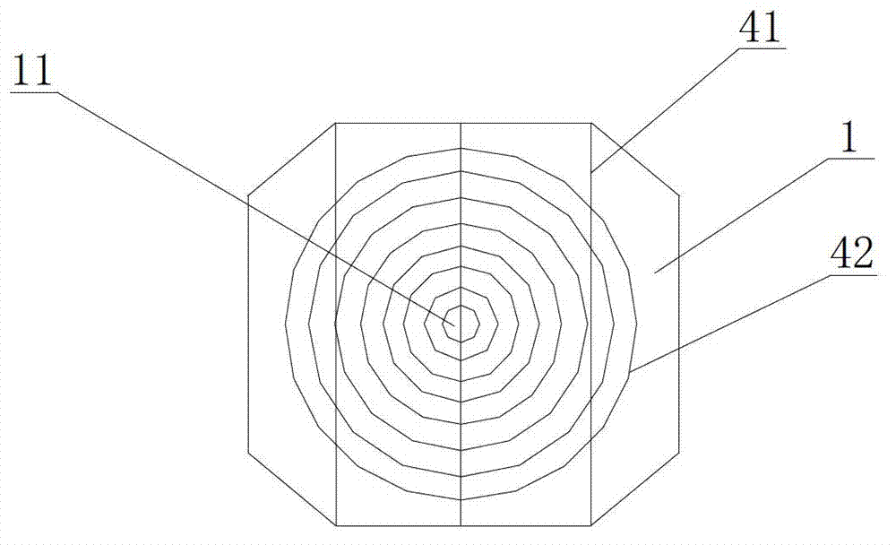
[0016] like figure 2 In the shown diffused fine grid wire battery, the front grid wire 4 is composed...


PUM

PropertyMeasurementUnit
Line widthaaaaaaaaaa

Abstract

The invention relates to a diffuse type fine grid line cell which comprises a cell sheet body, a connecting film attached to the back face of the cell sheet body, an insulating film arranged between the cell sheet body and the conducting film, front-face grid lines arranged on the front face of the cell sheet body and a back electrode arranged on the back face of the cell sheet body, wherein the center of the cell sheet body is provided with a center hole, the front-face grid lines are connected with the back electrode via the center hole, the front-face grid lines comprise at least one main grid line and at least one fine grid line in parallel, each fine grid line comprises a plurality of concentric circular grid lines, and the distance between two adjacent concentric circular grid lines is 1.2-1.3 mm. In the diffuse type fine grid line cell, the design of concentric circular grid lines is adopted, so that the power consumption can be reduced to minimum, the output power can be increased to maximum, the current collection quantity is increased, and the electrical property efficiency is improved.

Description

technical field [0001] The invention relates to the field of solar cells, in particular to a diffused fine grid cell. Background technique [0002] At present, in the industrialization technology of crystalline silicon solar cells, solar cells have the highest conversion efficiency and the most mature technology. However, compared with conventional energy sources, lower power generation efficiency and relatively higher cost restrict its development. Among the factors affecting efficiency The grid line of the cell is one of the key factors. The grid line design of the light-receiving surface of the solar cell is to collect the photocurrent to the maximum, that is, the grid line should be denser and thicker, the better, but this will inevitably reduce the light-receiving surface of the silicon cell. A well-designed grid line structure will minimize the series resistance of the battery, thereby minimizing power loss and maximizing output power. So far, when designing the grid l...

Claims


Application Information

Patent Timeline
IPC IPC(8): H01L31/0224
Inventor 王桂奋谢德兵王迎春
Owner ZNSHINE PV TECH
Learn More