Power network model-based wind power field automatic voltage control method

A technology of automatic voltage and control method, applied in wind power generation, single grid parallel feeding arrangement, reactive power compensation, etc., can solve the problems of unreasonable reactive power distribution, poor adjustment effect, increase of active power loss, etc.

Active Publication Date: 2012-12-19
北京中科伏瑞电气技术有限公司
View PDF4 Cites 27 Cited by
  • Summary
  • Abstract
  • Description
  • Claims
  • Application Information

AI Technical Summary

Problems solved by technology

In order to solve the problem of reactive power and voltage caused by a large amount of wind power entering the grid, some wind farms put into operation are equipped with dynamic reactive power compensation devices (SVC / SVG) with a certain capacity according to the grid dispatching requirements. (SVC / SVG) operate independently, and control according to their own control objectives and strategies. They fight each other, and the adjustment effect is very poor. It cannot meet the requirements of the power grid for the voltage fluctuation range of the wind power grid-connected point. Reasonably lead to an increase in active loss

Method used


Image

  • Power network model-based wind power field automatic voltage control method
  • Power network model-based wind power field automatic voltage control method
  • Power network model-based wind power field automatic voltage control method

Examples


Embodiment Construction

[0062] The principles and features of the present invention are described below in conjunction with the accompanying drawings, and the examples given are only used to explain the present invention, and are not intended to limit the scope of the present invention.

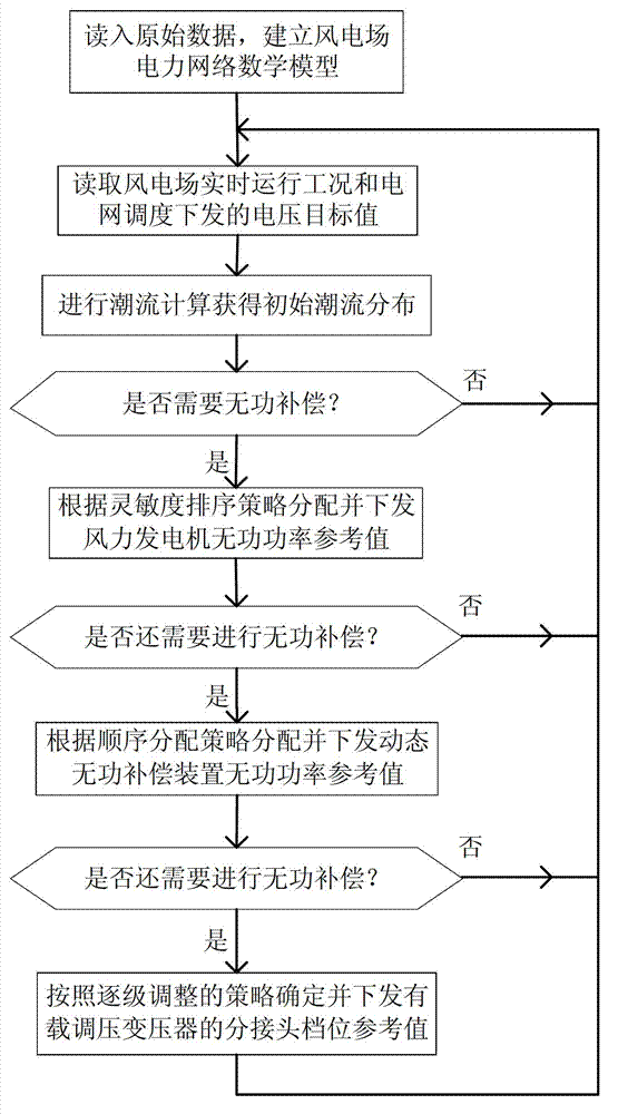
[0063] A method for automatic voltage control of a wind farm based on a power network model described in this embodiment, such as figure 1 shown, including the following steps:

[0064] Step 1, read the original data, and establish the mathematical model of the wind farm power network.

[0065] The mathematical model of the wind farm power network established in step 1 is the power flow equation:

[0066] I · = Y · U ·

[0067] In the formula is the node current column vector, is the nodal admittance matrix, is the node voltage column vector. The above formula is also:

[0068] ...


PUM


Abstract

The invention relates to a power network model-based wind power field automatic voltage control method which comprises the following steps of: 1, reading original data and building a wind power field power network mathematical model; 2, reading a wind power field real-time running working condition and a voltage target value released by the power grid dispatching; 3, carrying out load flow calculation to obtain initial load flow distribution on the basis of the former two steps; 4, distributing and releasing the reactive power reference value of a wind driven generator according to a sensitivity ordering strategy; 5, distributing and issuing the reactive power reference value of a dynamic reactive compensation device according to the sequence; and 6, confirming and releasing the tapping point gear reference value of an on-load tap changing transformer according to a step-by step adjustment strategy. According to the power network model-based wind power field automatic voltage control method, the unified coordination control among the reactive power of the wind power field wind driven generator, the reactive power of the dynamic reactive compensation device and the tapping joint of the on load tap changing transformer can be realized.

Description

technical field [0001] The invention relates to the technical field of wind power grid connection, in particular to an automatic voltage control method based on a power network model applied to a wind farm. Background technique [0002] In recent years, wind power generation has achieved tremendous development under the strong support of the state. With the continuous increase of wind power grid-connected capacity, due to the randomness and intermittent characteristics of wind energy and the operating characteristics of wind turbines, the impact on the grid voltage stability is also increasing. The problem of voltage stability is becoming more and more prominent, especially when large-scale wind power is connected to the weak terminal grid. In order to solve the problem of reactive power and voltage caused by a large amount of wind power entering the grid, some wind farms put into operation are equipped with dynamic reactive power compensation devices (SVC / SVG) with a certai...

Claims


Application Information

Patent Timeline
Patent Type & Authority Applications(China)
IPC IPC(8): H02J3/18H02J3/38
CPCY02E10/763Y02E40/30Y02E10/76
Inventor 侯佑华朱长胜蒿峰贺旭伟赵广弟
Owner 北京中科伏瑞电气技术有限公司
Why Eureka
Try Eureka