AM/Chirp modulation, realizing device thereof and emergency broadcast and communication system based on common AM/Chirp modulation
A modulated baseband, common technology, applied in the field of emergency broadcasting system, can solve the problems of complex composition, uncomfortable working for a long time, high power consumption, etc.
- Summary
- Abstract
- Description
- Claims
- Application Information
AI Technical Summary
Problems solved by technology
Method used
Image
Examples
Embodiment 1
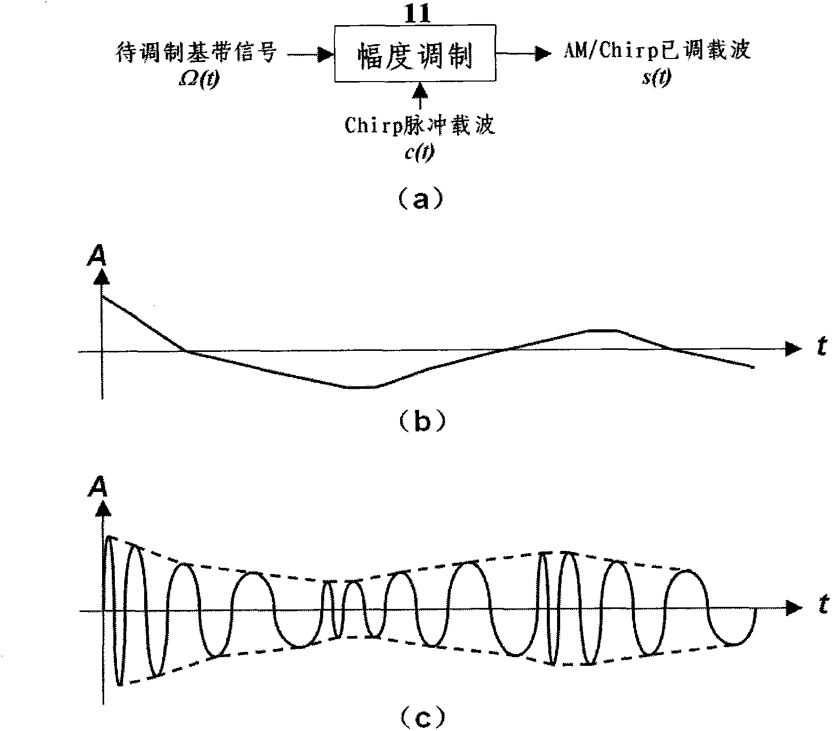
[0069] This embodiment is used to illustrate the implementation process of AM / Chirp modulation provided by the present invention. see figure 1 As shown in (a), the baseband signal Ω(t) to be modulated is sent into the amplitude modulator (11) to carry out amplitude modulation on the Chirp pulse carrier c(t) used as the primary modulation carrier, and the amplitude modulator (11) outputs The composite modulated carrier s(t) of is used as the communication signal.
[0070] When the specific method of amplitude modulation on the Chirp pulse carrier c(t) is ordinary AM modulation, the formed composite modulated carrier s(t) (that is, ordinary AM / Chirp modulated carrier) is as follows figure 1 (c) shown. Obviously, ordinary AM / Chirp modulation is to replace the sinusoidal carrier in traditional ordinary AM modulation with Chirp pulse carrier. Since the Chirp pulse carrier is a broadband signal, the ordinary AM / Chirp modulated carrier is also a broadband signal. Since the carrie...
Embodiment 2
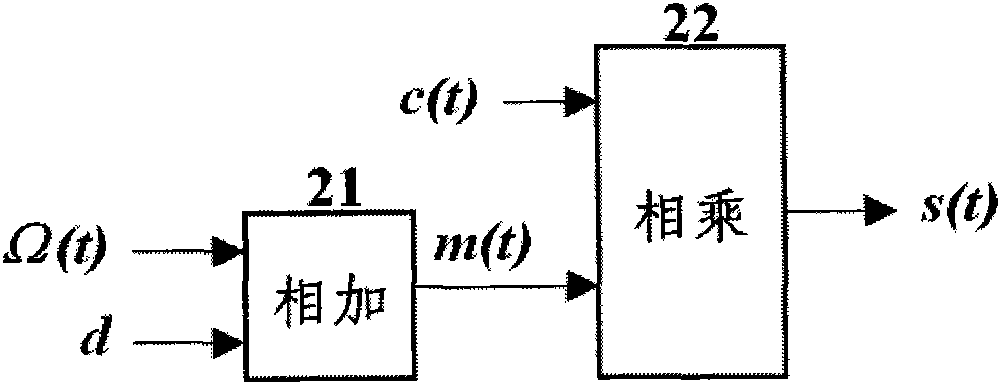
[0072] This embodiment is used to illustrate the implementation method of the first common AM / Chirp modulator provided by the present invention. The analog multiplier chip MC1496 / MC1596 produced by MOTOROLA can be used to realize such as figure 2 The signal processing functions of the adder (21) and the multiplier (22) in the shown AM / Chirp modulator; Continue to use the existing common AM modulator that adopts MC1496 / MC1596 to build, adopt Chirp pulse carrier as the modulation carrier, then its The multiplication result of the output is the ordinary AM / Chirp modulated carrier; by adjusting the position of the zero adjustment potentiometer between the 1st and 4th pins to make the DC component 0, DSB / Chirp modulation can also be realized.
Embodiment 3
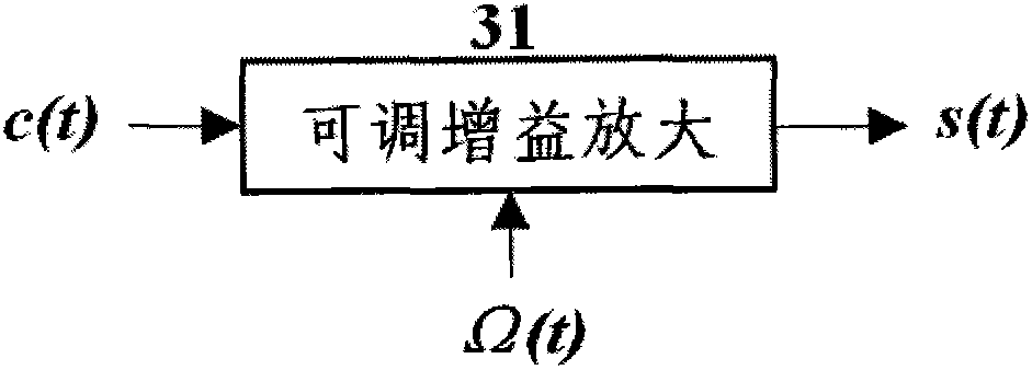
[0074] This embodiment is used to illustrate the implementation method of the second common AM / Chirp modulator provided by the present invention. The traditional collector amplitude modulation circuit can realize such image 3 Shown variable gain amplifier (31); but, when the bandwidth of the Chirp pulse carrier used as the modulation carrier is larger, then need to represent the LC resonant coil on the collector in the collector amplitude modulation circuit with resistance. The RF2516 chip produced by RFMD can also be used to implement such as image 3 The variable gain amplifier (31) in the common AM / Chirp modulator shown can also take into account the generation of Chirp pulse carrier; wherein, the baseband signal to be modulated is input from the modulation terminal (the 8th pin) to control its reference oscillation circuit (The first pin OSCB and the second pin OSCE) the parameter of the reactance element (typically capacitance value) changes according to the sweeping ru...
PUM
 Abstract
Description
Claims
Application Information
 - R&D
- Intellectual Property
- Life Sciences
- Materials
- Tech Scout
- Unparalleled Data Quality
- Higher Quality Content
- 60% Fewer Hallucinations
Browse by: Latest US Patents, China's latest patents, Technical Efficacy Thesaurus, Application Domain, Technology Topic, Popular Technical Reports.
© 2025 PatSnap. All rights reserved.Legal|Privacy policy|Modern Slavery Act Transparency Statement|Sitemap|About US| Contact US: help@patsnap.com


