Tight braking device for numeric control rotary table

A technology of numerical control turntable and rotary table, which is applied in the direction of large-scale fixed members, metal processing machinery parts, metal processing equipment, etc., can solve the problems of reduced precision of processed workpieces, deviation in the circumferential direction of oil cylinders, and low reliability of brake tightness, etc., to achieve Improved rigidity, high braking force, and high braking reliability

Inactive Publication Date: 2012-12-26
NINGBO HAITIAN PRECISION MASCH CO LTD
View PDF6 Cites 8 Cited by
  • Summary
  • Abstract
  • Description
  • Claims
  • Application Information

AI Technical Summary

Problems solved by technology

However, the problem with the existing braking device is that when the oil cylinder acts on the friction plate, since the piston of the oil cylinder extends into the piston hole on the base, the axial movement of the piston in the piston hole drives the oil cylinder to move up and down. Therefore, there is no binding force in the circumferential direction of the oil cylinder. Due to the influence of the friction force between the oil cylinder and the friction plate, driven by the rotary disc, the oil cylinder is easily shifted along its circumferential direction, resulting in reliable braking. The performance is not high, which will have a negative impact on the performance of the CNC turntable, resulting in a reduction in the accuracy of the workpiece

Method used


Image

  • Tight braking device for numeric control rotary table
  • Tight braking device for numeric control rotary table

Examples


Embodiment 1

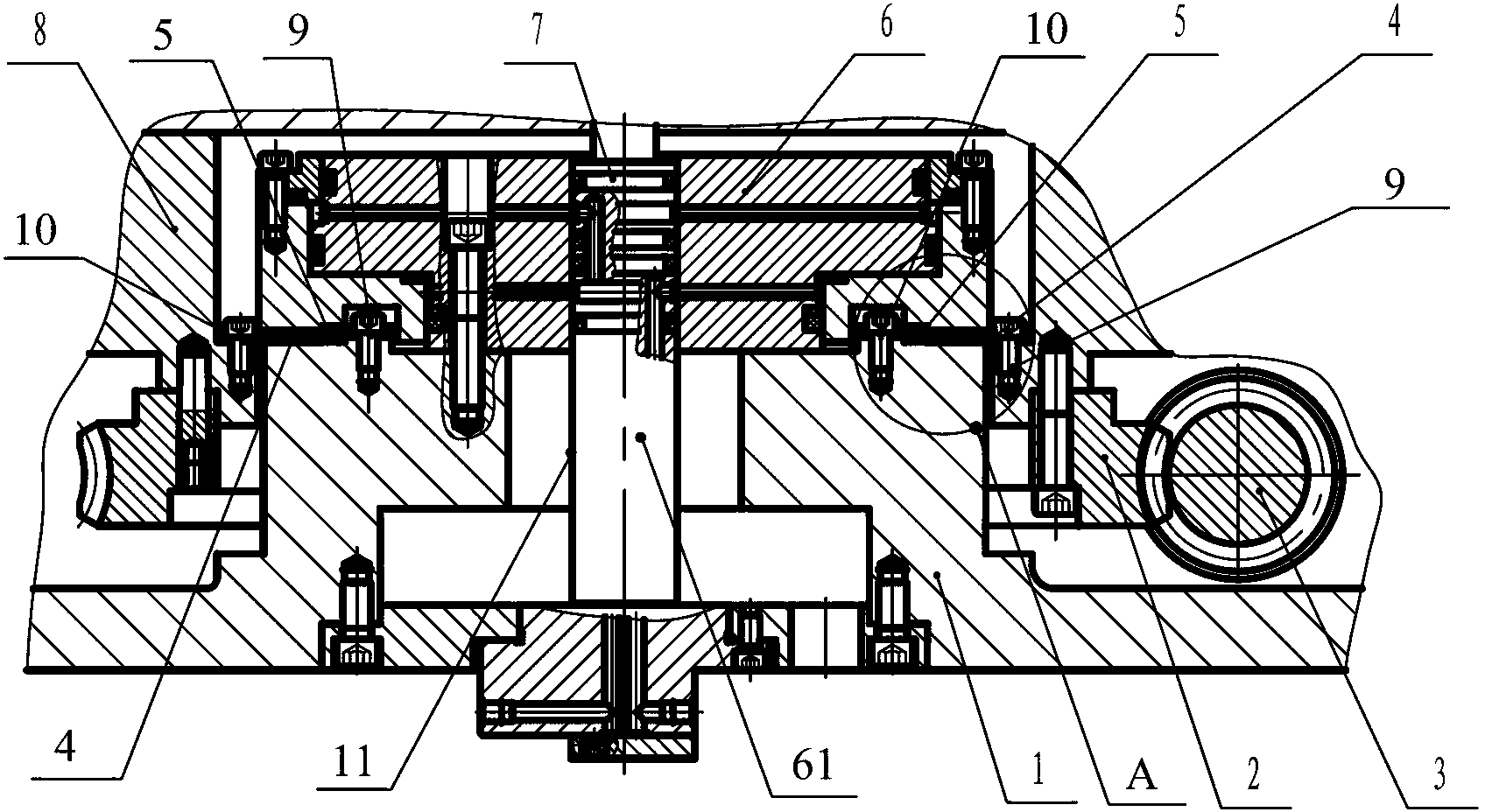
[0016] Embodiment 1: As shown in the figure, a braking device for a numerically controlled turntable includes a base 1, an oil cylinder 6, an oil separator 7 and a first annular friction plate 4 fixedly arranged on a rotary disc 8. The base 1 is provided with Piston hole 11, the piston 61 of the oil cylinder 6 extends into the piston hole 11, the oil cylinder 6 is connected with the oil separator 7, the first annular friction plate 4 is located between the base 1 and the oil cylinder 6, the first annular friction plate 4 and the oil cylinder 6 A second annular friction plate 5 is arranged between them, and the second annular friction plate 5 is fixedly arranged on the base 1 .

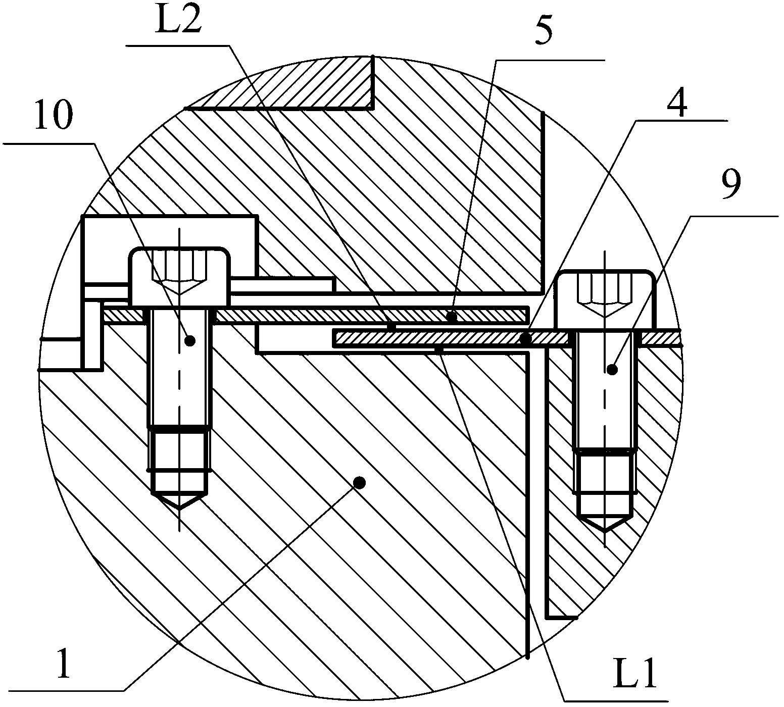
[0017] In this embodiment, a first gap L1 is provided between the first annular friction plate 4 and the base 1, a second gap L2 is provided between the first annular friction plate 4 and the second annular friction plate 5, and the first gap L1 is 0.05mm, and the second gap L2 is 0.05mm.

[0018] In ...

Embodiment 2

[0019] Embodiment 2: As shown in the figure, a braking device for a numerically controlled turntable includes a base 1, an oil cylinder 6, an oil separator 7 and a first annular friction plate 4 fixedly arranged on a rotary disc 8. The base 1 is provided with Piston hole 11, the piston 61 of the oil cylinder 6 extends into the piston hole 11, the oil cylinder 6 is connected with the oil separator 7, the first annular friction plate 4 is located between the base 1 and the oil cylinder 6, the first annular friction plate 4 and the oil cylinder 6 A second annular friction plate 5 is arranged between them, and the second annular friction plate 5 is fixedly arranged on the base 1 .

[0020] In this embodiment, a first gap L1 is provided between the first annular friction plate 4 and the base 1, a second gap L2 is provided between the first annular friction plate 4 and the second annular friction plate 5, and the first gap L1 is 0.1 mm, and the second gap L2 is 0.1 mm.

[0021] In ...

Embodiment 3

[0022] Embodiment 3: As shown in the figure, a braking device for a numerically controlled turntable includes a base 1, an oil cylinder 6, an oil separator 7, and a first annular friction plate 4 fixedly arranged on a rotary disc 8. The base 1 is provided with Piston hole 11, the piston 61 of the oil cylinder 6 extends into the piston hole 11, the oil cylinder 6 is connected with the oil separator 7, the first annular friction plate 4 is located between the base 1 and the oil cylinder 6, the first annular friction plate 4 and the oil cylinder 6 A second annular friction plate 5 is arranged between them, and the second annular friction plate 5 is fixedly arranged on the base 1 .

[0023] In this embodiment, a first gap L1 is provided between the first annular friction plate 4 and the base 1, a second gap L2 is provided between the first annular friction plate 4 and the second annular friction plate 5, and the first gap L1 is 0.15mm, and the second gap L2 is 0.15mm.

[0024] In...


PUM


Abstract

The invention discloses a tight braking device for a numeric control rotary table. The tight braking device comprises a base, an oil cylinder, an oil separator and a first annular friction plate, wherein the first annular friction plate is fixedly arranged on a rotary disk; a piston hole is formed in the base; a piston of the oil cylinder extends into the piston hole; the oil cylinder is connected with the oil separator; the first annular friction plate is positioned between the base and the oil cylinder; and a second annular friction plate is arranged between the first annular friction plate and the oil cylinder and is fixedly arranged on the base. The tight braking device has the advantages that the oil cylinder directly acts on the second annular friction plate; the second annular friction plate is fixed on the base; the base is immovable and constraints the circumferential direction of the second annular friction plate; during tight braking, the oil cylinder and the second annular friction plate are positioned in a communicated static state; and when the first annular friction plate which is fixed with the rotary disk together is simultaneously subjected to action forces of two friction surfaces, a braking force is greater and the tight braking reliability is high. Therefore, the rigidity of the numerical control rotary table is improved and the guarantee for machining workpieces with high precision by the machine tool is provided.

Description

technical field [0001] The invention relates to a braking device, in particular to a braking device for a numerical control turntable. Background technique [0002] With the rapid development of my country's automobile, military industry, shipbuilding, aerospace, energy, environmental protection and other industries, the demand for horizontal machining centers in the domestic market is increasing. As the key functional part of the horizontal machining center, the CNC turntable directly affects the machining quality of the workpiece. The brake function is one of the necessary functions of various CNC turntables. When the CNC turntable does not participate in angle indexing or circular interpolation, in order to ensure that the turntable has no angular displacement during processing and improve its ability to withstand eccentric loads, generally Equipped with brake device. The reliability of the braking device directly affects the performance of the CNC turntable. The exist...

Claims


Application Information

Patent Timeline
Patent Type & Authority Applications(China)
IPC IPC(8): B23Q1/26
Inventor 赵永进
Owner NINGBO HAITIAN PRECISION MASCH CO LTD
Why Eureka
Try Eureka