Coiling shaft, end cover, safety belt coiling device and safety belt assembly
A retractor and seat belt technology, applied in the field of seat belts, achieves the effects of safe and stable use, not easy to bend and deform, and simplified overall stress conditions
- Summary
- Abstract
- Description
- Claims
- Application Information
AI Technical Summary
Problems solved by technology
Method used
Image

Examples
Embodiment Construction
[0041] In the following description, numerous specific details are set forth in order to provide a thorough understanding of the present invention. However, the present invention can be implemented in many other ways different from those described here, and those skilled in the art can make similar extensions without violating the connotation of the present invention, so the present invention is not limited by the specific implementations disclosed below.
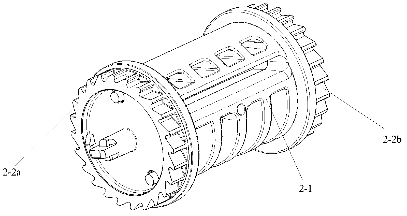
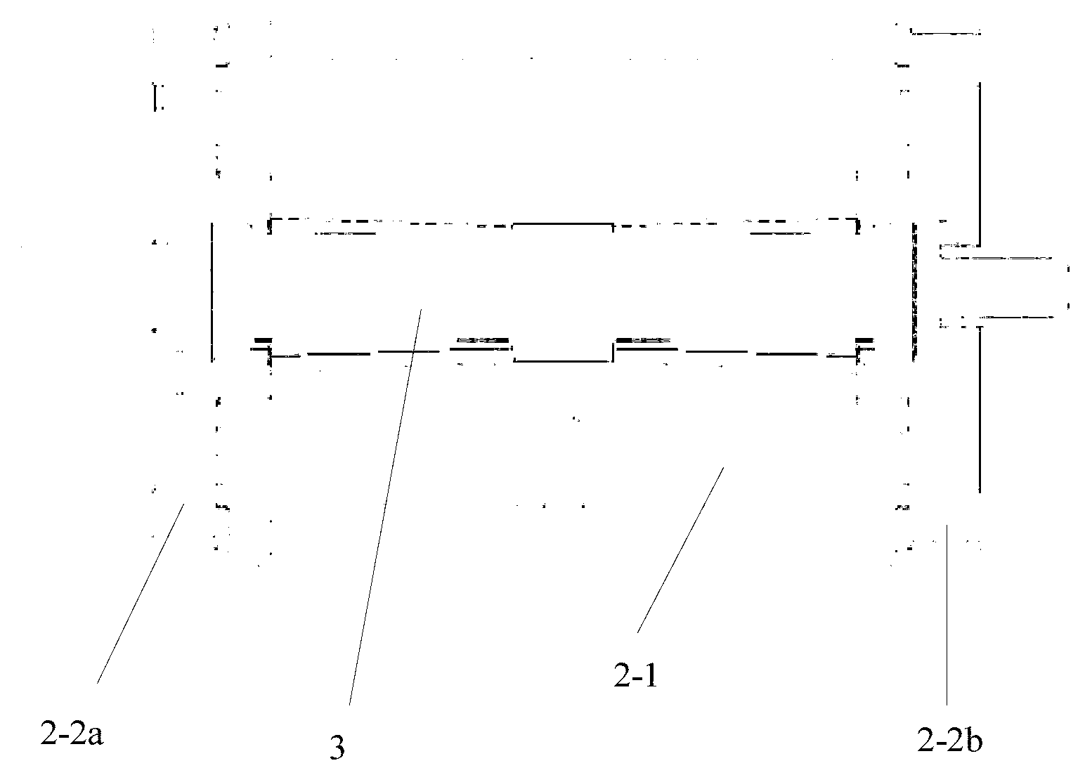
[0042] Please see figure 2 , image 3 and Figure 4 ,in, figure 2 It is a schematic diagram of an embodiment of the reel for the seat belt retractor of the present invention. image 3 for figure 2 A cross-sectional view along the axis of the reel; Figure 4 An exploded view of the assembly for the reel and torsion bar.
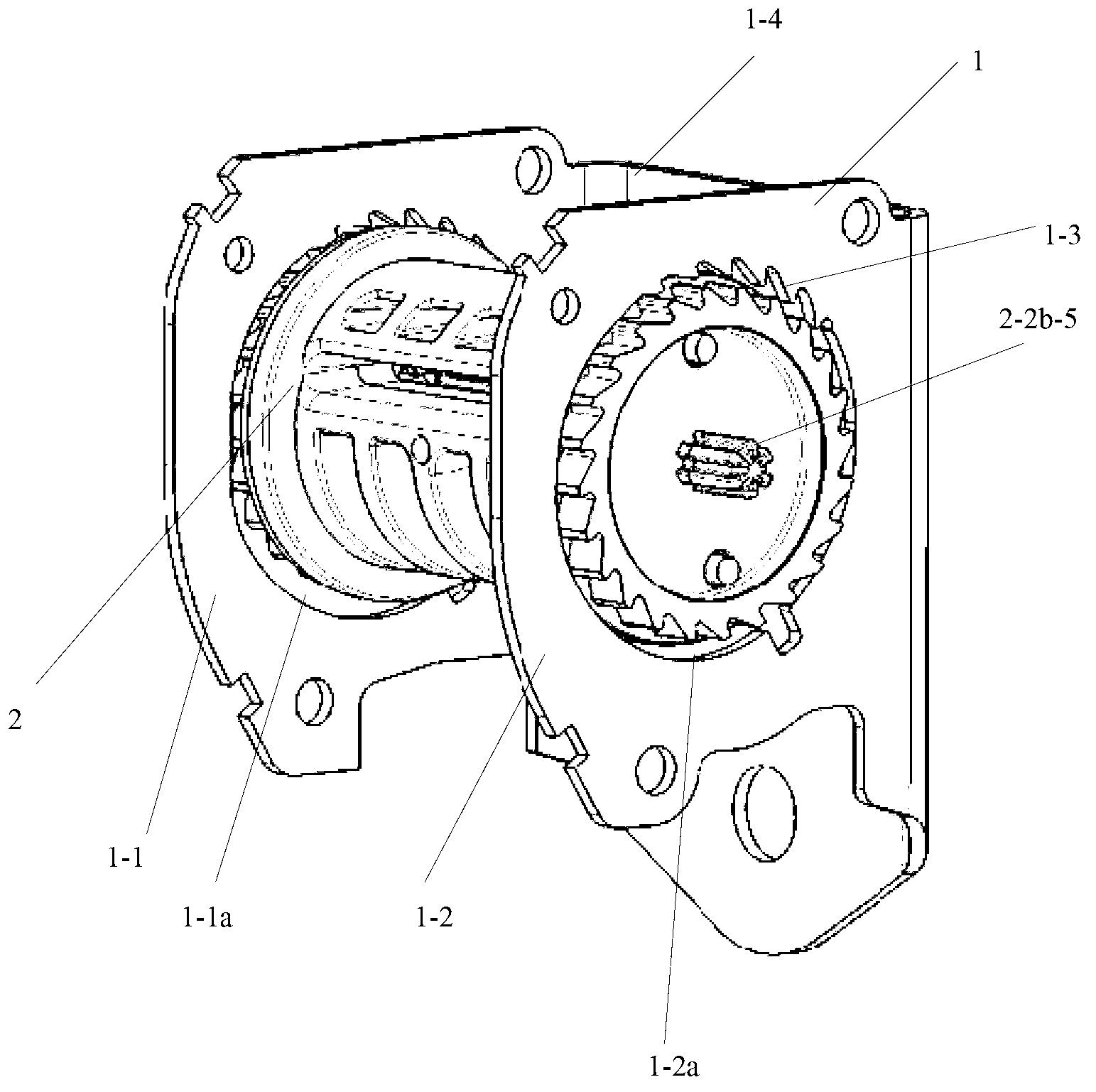
[0043] The reel 2 includes a mandrel 2-1 and end caps detachably arranged at both ends of the mandrel 2-1: a left end cap 2-2a and a right end cap 2-2b. The mandrel 2-1 is used for winding the web...
PUM
 Abstract
Description
Claims
Application Information
PatSnap Eureka turns technology decisions into work you can execute. Powered by our Innovation Knowledge Graph, it runs expert workflows across engineering, life sciences, materials and intellectual property. Get your review-ready output in minutes.


