Hydraulic fracturing ground stress testing device with equal diameter design

A technology for testing equipment and in-situ stress, which is applied in the direction of mining fluid, wellbore/well components, earthwork drilling and production, etc. It can solve the problems of testing equipment stuck, unable to be retracted to the ground, and testing equipment falling into holes, etc., to achieve high overall rigidity , Eliminate water leakage and pressure leakage and test failure, and the effect of not being easy to bend and deform

Pending Publication Date: 2018-11-06
地泰科学仪器(武汉)有限公司
View PDF3 Cites 6 Cited by
  • Summary
  • Abstract
  • Description
  • Claims
  • Application Information

AI Technical Summary

Problems solved by technology

There is a large gap between the connecting unit of the thinner fracturing section and the wall of the borehole. When the rock mass of the drill hole is incomplete, the debris and rock blocks generated by the shedding of the rock mass of the hole wall will accumulate in the above gap, causing the test The equipment is stuck and cannot be retracted to the ground, causing the test equipment to fall into the hole accident

Method used


Image

  • Hydraulic fracturing ground stress testing device with equal diameter design
  • Hydraulic fracturing ground stress testing device with equal diameter design
  • Hydraulic fracturing ground stress testing device with equal diameter design

Examples


Embodiment Construction

[0023] In order to make the technical means, creative features, goals and effects achieved by the present invention easy to understand, the following will further explain how the present invention is implemented in conjunction with the accompanying drawings and specific implementation methods.

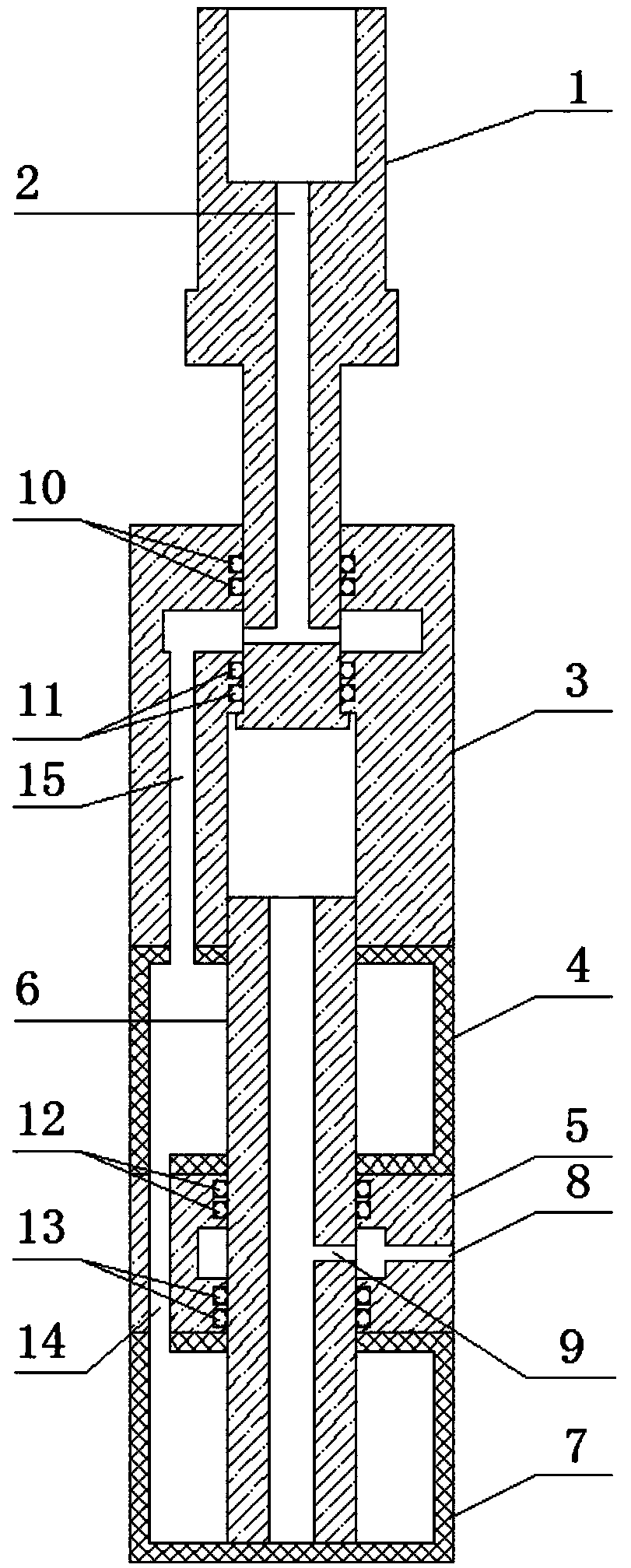
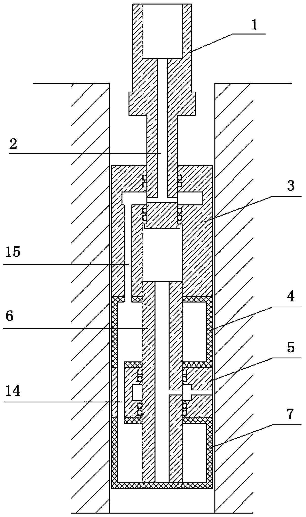
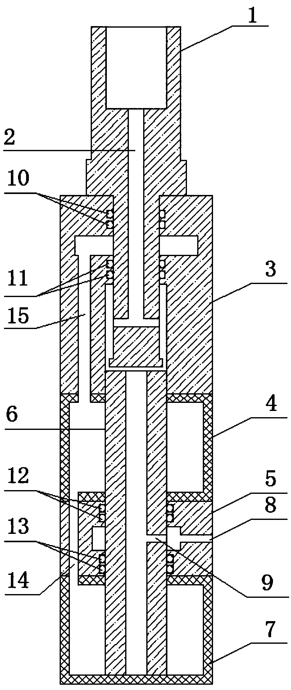
[0024] Such as Figure 1 to Figure 4 As shown, the present invention provides a hydraulic fracturing ground stress testing device with an equal diameter design, including a sliding valve column 1, a valve seat 3, an upper packer 4, a cracking flower tube 5, a central rod 6 and a lower Packer 7, the sliding spool 1 is installed in the valve seat 3 and protrudes from the upper end of the valve seat 3 to connect to the lower end of the drill pipe (not shown in the figure), and the spool water hole 2 is opened in the sliding spool 1 , the water hole 2 of the spool communicates with the inner hole of the drill pipe 16, the central rod 6 is connected to the lower end of the valve seat 3, the...


PUM


Abstract

The invention discloses a hydraulic fracturing ground stress testing device with equal diameter design. The hydraulic fracturing ground stress testing device comprises a sliding valve rod, a valve seat, an upper packer, a lower packer, a fracturing shock tube and a central rod. The sliding valve rod is disposed in the valve seat in a penetrating mode and extends out of the upper end to be connected to the lower end of a drill pipe. The sliding valve rod is internally provided with a valve rod water hole communicating with an inner hole of the drill pipe. The central rod is connected to the lower end of the valve seat and is sleeved with the upper and lower packers and the fracturing shock tube. The valve seat, the upper and lower packers and the fracturing shock tube have the same outer diameter. An L-shaped through hole communicating an inner cavity of the valve seat with an inner cavity of the upper packer is formed in the valve seat. A packer communicating hole communicating an inner cavity of the upper packer with an inner cavity of the lower packer is formed in one side of the fracturing shock tube, a fracturing water hole communicating with an inner hole of the central rod isformed in the other side of the fracturing shock tube. The sliding valve rod is provided with two stations including an upper station and a lower station in the inner cavity of the valve seat, and asingle loop is achieved. The hydraulic fracturing ground stress testing device with the equal diameter design has the advantages that the appearance is attractive, bending and deformation are not prone to occurring, and the phenomenon of getting stuck in a drill hole is not prone to occurring.

Description

technical field [0001] The invention relates to the technical field of in-situ stress field testing by hydraulic fracturing, in particular to an in-situ stress testing device for boreholes with equal diameters and hydraulic fracturing. Background technique [0002] During the in-situ stress test of the hydraulic fracturing method, it is necessary to pressurize the upper and lower packers connected in series first, so that the upper and lower packers expand to form a closed fracturing section between them, and then apply pressure to the closed fracturing section. pressure to form tension fractures in the drilled rock mass. Therefore, all devices for in-situ stress testing in boreholes need to be provided with a waterway switching valve on the upper part, in order to achieve the purpose of pressurizing the above two pressure circuits respectively by using the drill pipe waterway. [0003] In the traditional hydraulic fracturing stress testing device, the pressure connection b...

Claims


Application Information

Patent Timeline
Patent Type & Authority Applications(China)
IPC IPC(8): E21B49/00E21B43/26
CPCE21B49/00E21B43/26
Inventor 不公告发明人
Owner 地泰科学仪器(武汉)有限公司
Why Eureka
Try Eureka