Liquid hydrostatic bearing capable of realizing oil distribution from end surface

A hydrostatic bearing and liquid technology, applied in the field of bearing components, can solve problems such as inconvenient installation, disassembly and cleaning, difficult oil pressure consistency, increased cost, etc., to achieve convenient disassembly and cleaning and later maintenance, ensure consistency, and reduce costs Effect

Active Publication Date: 2012-12-26
HUAZHONG UNIV OF SCI & TECH
View PDF6 Cites 20 Cited by
  • Summary
  • Abstract
  • Description
  • Claims
  • Application Information

AI Technical Summary

Problems solved by technology

At present, most hydrostatic bearings supply oil to two/four oil chambers through two/four hydraulic pumps, which not only increases the cost, but also makes it difficult to ensure the consistency of oil pressure in each oil chamber
In addition, some hydrostatic bearings realize the oil supply to the oil chamber through the grooves on the outer surface of the bearing and/or the inner surface of the bearing seat, which requires the bearing seat to be designed as an integrated structure, and it is inconvenient to install, disassemble and clean.
For example, the patent application with the application number CN200610032309.4 discloses an oil return hydrostatic bearing with an outer clearance throttling

Method used


Image

  • Liquid hydrostatic bearing capable of realizing oil distribution from end surface
  • Liquid hydrostatic bearing capable of realizing oil distribution from end surface

Examples


Embodiment Construction

[0030] In order to make the object, technical solution and advantages of the present invention clearer, the present invention will be further described in detail below in conjunction with the accompanying drawings and embodiments. It should be understood that the specific embodiments described here are only used to explain the present invention, not to limit the present invention.

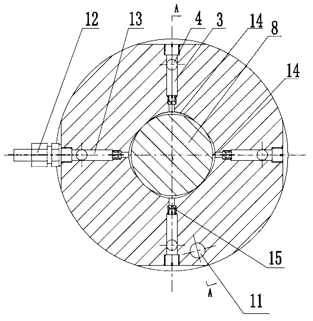
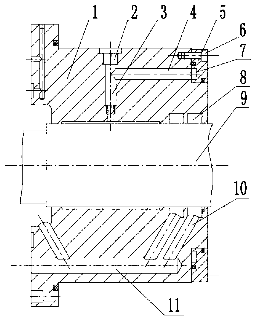
[0031] figure 1 is a schematic diagram of the main structure of the hydrostatic bearing according to the present invention. like figure 1 As shown in , the hydrostatic bearing according to the present invention mainly includes a bearing body 1, a plurality of bearing oil chambers 14 located on the inner surface of the bearing body 1 and evenly distributed along the bearing circumferential direction (in figure 1 shown as 4, and can also be designed as other numbers, such as 3, 6, etc.), the oil inlet piping system for delivering hydraulic oil to each bearing oil chamber 14, and for sending the use...


PUM


Abstract

The invention discloses a liquid hydrostatic bearing capable of realizing oil distribution from an end surface. The liquid hydrostatic bearing comprises a bearing body, a plurality of bearing oil cavities, a matched oil inlet pipeline system and oil return pipeline system, wherein the oil inlet pipeline system comprises an oil inlet, a main oil inlet channel with one end connected with the oil inlet and the other end connected with one bearing oil cavity, subsidiary oil inlet channels arranged corresponding to the rest of the bearing oil cavities and communicated with each other, and oil transportation channels. The number of the oil transportation channels corresponds to that of the oil inlet channels. The oil transportation channels are arranged along the axial direction of the hydrostatic bearing; one end of each oil transportation channel is communicated with each oil inlet channel; and the other end of each oil transportation channel is communicated with circular grooves disposed on the inner surface of an end cap arranged at one end of the bearing. The oil distribution from the end surface can be realized through a single hydraulic pump. The liquid hydrostatic bearing is convenient for guaranteeing consistence of pressure in each bearing oil cavity, has compact whole structure and good processing performance, and is suitable for various high-precision bearing works.

Description

technical field [0001] The invention relates to the field of bearing components, in particular to a hydrostatic bearing capable of realizing oil distribution on the end face. Background technique [0002] In modern machine manufacturing, hydrostatic bearings are widely used. The so-called hydrostatic bearing uses an external oil supply device to deliver hydraulic oil to the bearing through a throttle at a certain pressure, forming a hydraulic oil layer with pressure in the bearing oil chamber, and correspondingly floats the shaft to have a load-carrying capacity. plain bearings. Its specific working principle is: when the shaft center installed in the bearing has no displacement, the clearance around the bearing is equal, and the flow resistance is also equal, so the pressure of each oil chamber is equal, and the bearing does not bear external load; and when the shaft When the center is displaced, the bearing gap facing the displacement direction decreases, the flow resist...

Claims


Application Information

Patent Timeline
IPC IPC(8): F16C32/06F16C33/00B23B19/02
Inventor 黄禹邵新宇张国军柳懿麟张尚李明震丁劲峰
Owner HUAZHONG UNIV OF SCI & TECH
Why Eureka
Try Eureka