Maintenance standby system for cooling water system of nuclear power plant

A cooling water system and backup system technology, which is applied to auxiliary equipment of nuclear power plants, nuclear power generation, nuclear engineering, etc. Operation, circuit A or circuit B cannot operate normally, etc., to shorten the maintenance cycle, improve safety and reliability, and optimize the maintenance path.

Inactive Publication Date: 2012-12-26
SHANGHAI NUCLEAR ENG RES & DESIGN INST CO LTD
View PDF4 Cites 12 Cited by
  • Summary
  • Abstract
  • Description
  • Claims
  • Application Information

AI Technical Summary

Problems solved by technology

The loop A and loop B of some nuclear power plants adopt the water supply mode of common main pipe 3, 5, 11, 12, 13, and 15 (see figure 1 ), while loop A and loop B must maintain continuous operation during the entire operating life of the nuclear power plant, therefore, it will result in failure to control the common main pipe 3, 5, 11, 12, 13, 15, and all isolation valves connected 2, 6, 10, etc. for isolated maintenance or replacemen...

Method used


Image

  • Maintenance standby system for cooling water system of nuclear power plant
  • Maintenance standby system for cooling water system of nuclear power plant

Examples


Embodiment Construction

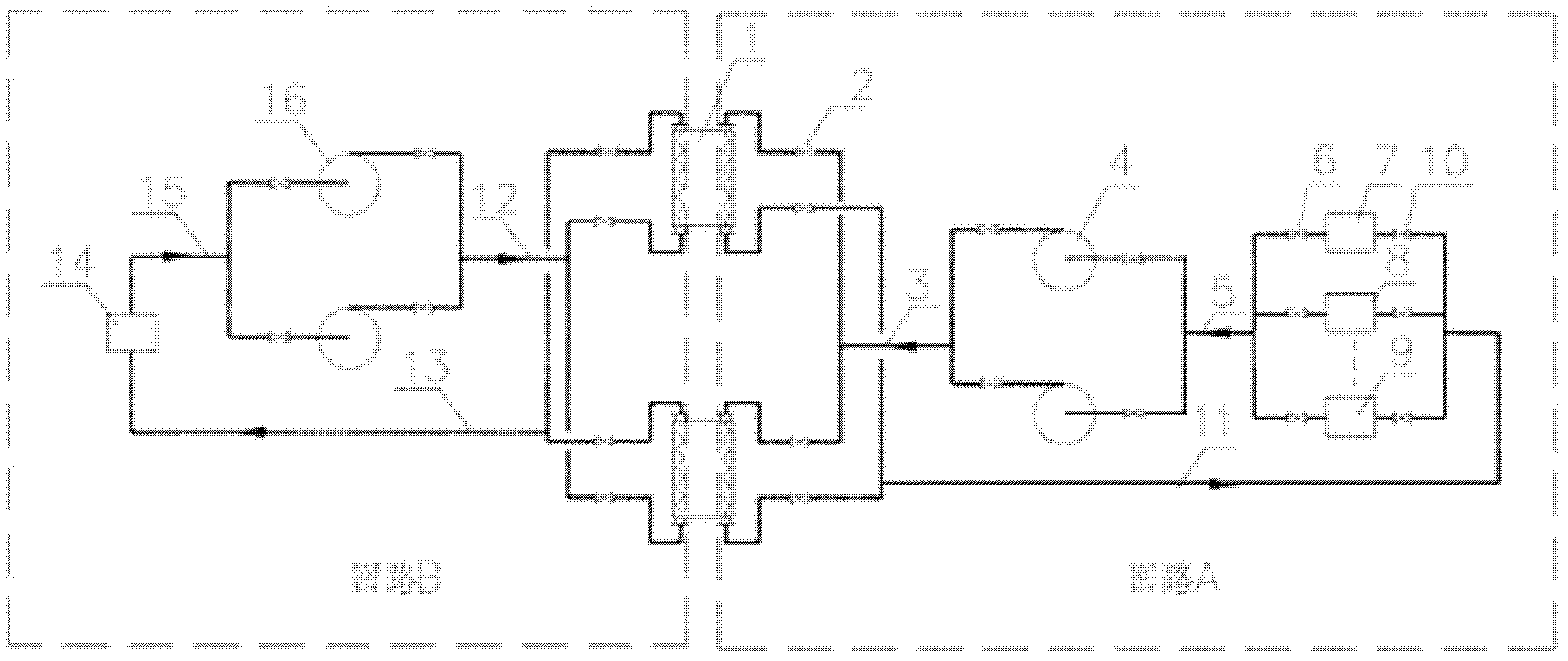
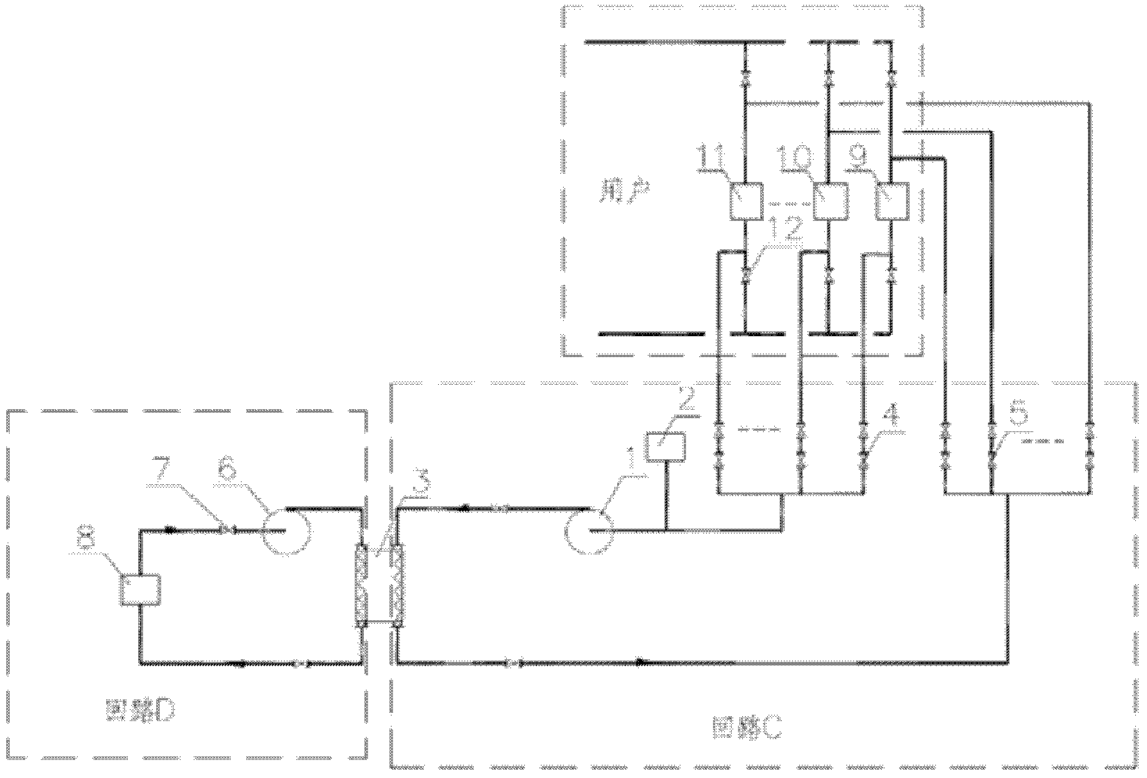
[0019] exist figure 2 The loop of the cooling water system of the nuclear power plant is not shown in the figure. In the following description, the loop of the cooling water system of the nuclear power plant is directly referred to as figure 1 The circuit shown is for illustration. but, figure 1 and figure 2 The reference signs in should be treated separately, in figure 1 and figure 2 The same reference numbers do not necessarily identify the same components.

[0020] Such as figure 2 As shown, the maintenance backup system is composed of loop C (third loop) and loop D (fourth loop). Loop C will supply cooling water system users 9, 10, and 11 (of loop A or loop B) that must supply water when the reactor is shut down for maintenance. The heat of the user) is transferred to the circuit D through the intermediate heat exchanger 3, and the circuit D releases the heat to the final heat sink 8 (such as the atmosphere or the sea, a large river, etc.). Loop C is a closed lo...


PUM


Abstract

The invention relates to a maintenance standby system for a cooling water system of a nuclear power plant, which can solve the maintenance problem of a public main pipe of the cooling water system of the nuclear power plan and a valve connected with the public main pipe. The cooling water system of the nuclear power plant comprises a loop A and a loop B, wherein the loop A is connected with cooling water system users, and the loop A is a cooling water circulation pipeline; the loop A is connected with the loop B through an intermediate heat exchanger, and the loop B is connected with an ultimate hot trap; the loop A and the loop B respectively adopt water supply pipelines of the public main pipe; and at least part of the public main pipe is connected with isolating valves. The maintenance standby system comprises a loop C and a loop D, wherein pipelines of the loop C are directly connected into the cooling water system users connected with the loop. Each cooling water system user is provided with isolating valves in front and back of the loop C side, and the loop C is a cooling water circulation pipeline and is completely independent of the loop A and the loop B. The loop C is connected with the loop D through the intermediate heat exchanger, and the loop D is connected with the ultimate hot trap.

Description

technical field [0001] The invention relates to a standby system for maintenance of a cooling water system of a nuclear power plant. Background technique [0002] During the entire operating life of a nuclear power plant, including shutdown, power operation, or accidental operation, the cooling water system is required to dissipate the core decay heat of the unit, the decay heat of the spent fuel pool, and the heat of other equipment (hereinafter collectively referred to as nuclear power plants) heat) to the ultimate heat sink (such as the atmosphere or the sea, large rivers, etc.). The cooling water system of a general nuclear power plant is divided into two loops, loop A (first loop) and loop B (second loop) (see figure 1 ), the loop A transfers the heat from the nuclear power plant to the loop B through the intermediate heat exchanger 1, and the loop B releases the heat from the nuclear power plant to the final heat sink 14. It should be noted that there are two or more...

Claims


Application Information

Patent Timeline
IPC IPC(8): G21D1/02G21C17/017
CPCY02E30/40Y02E30/00Y02E30/30
Inventor 宋春景邢晓峰吴双黄灿华马旭升袁义华朱立群葛鸿辉王岳郑毅斌徐传力张志超徐进马娟曹震李震邰泱海陆帆
Owner SHANGHAI NUCLEAR ENG RES & DESIGN INST CO LTD
Why Eureka
Try Eureka