Connection structure of connection end of component and connection terminal

A connection structure and terminal button technology, which is applied in connection, electrical components, clamping/spring connection, etc., can solve the problems of insufficient stability, false welding at the welding place, separation from the base material, etc., and achieve a highly stable working state, The effect of prolonging the service life and saving electric energy

Active Publication Date: 2012-12-26
TONGXIANG WEIDA ELECTRONICS
View PDF7 Cites 6 Cited by
  • Summary
  • Abstract
  • Description
  • Claims
  • Application Information

AI Technical Summary

Problems solved by technology

This type of connection structure needs to be soldered with silver solder at the contact point between the connection end of the device and the step or side surface of the terminal button, and the surface after welding needs to be cleaned and anti-oxidation treatment; especially when the surface of the terminal button is electroplated, the electroplating Under high-temperature welding, the layer sometimes breaks away from the base material, loosens, and falls off, which affects the normal use of the device. For example, there is dirt on the surface of the terminal button, and there is false welding at the welding place. It is difficult to achieve consistency in the welding hot-melt process, for example When used as measurement, metering and control components, the accuracy and stability are not high enough

Method used


Image

  • Connection structure of connection end of component and connection terminal
  • Connection structure of connection end of component and connection terminal
  • Connection structure of connection end of component and connection terminal

Examples


Embodiment 1

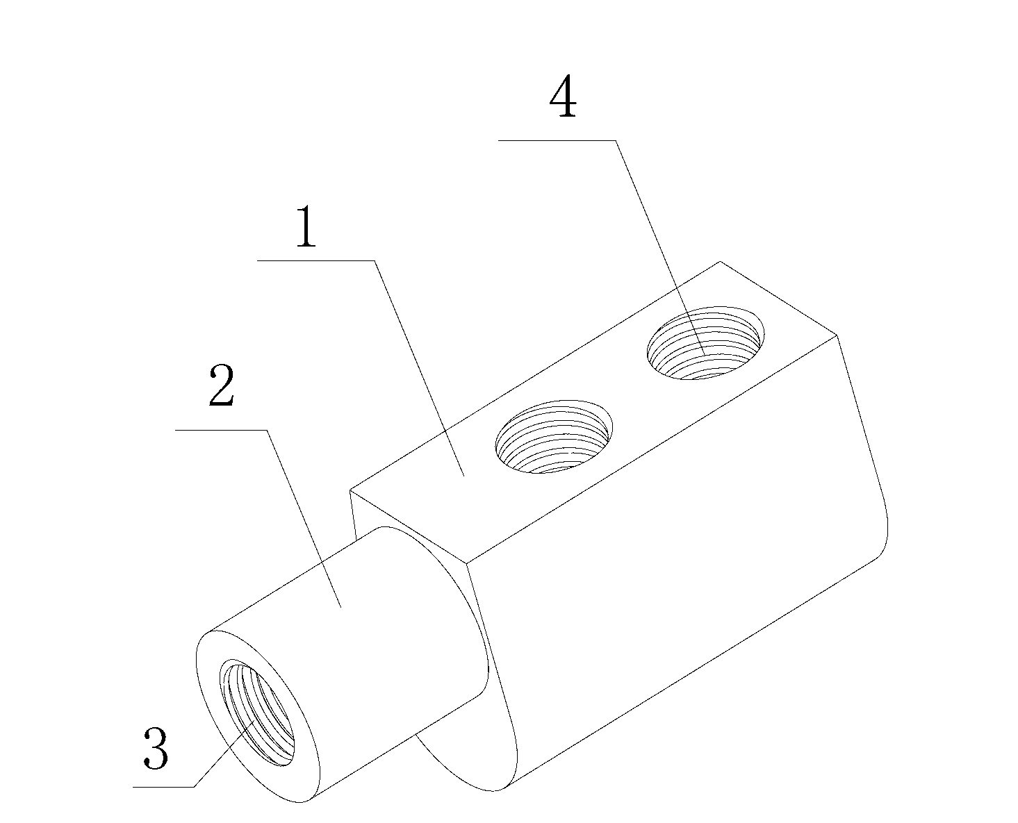
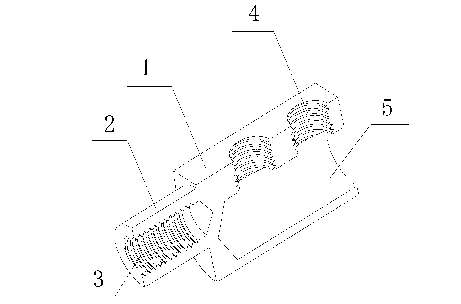
[0029] figure 1 , figure 2 As shown in , the axial end of the terminal button 1 is provided with a cylindrical column 2, and the center of the cylindrical column 2 is provided with a connecting hole 3, and the inner wall of the connecting hole 3 is provided with a radial groove, and the other axial end of the terminal button 1 One end is provided with a wiring hole 5 for external power input and output of the instrument, and a screw hole 4 is provided in the radial direction of the input and output wiring hole 5. The screw hole 4 is used to fix the external power input and output lines with screws. The connection hole 3 and the wiring hole The two holes of 5 are not connected to each other. Technically, the air outside the meter is blocked from entering the inside of the meter, which corrodes the internal components and prolongs the service life of the meter.

Embodiment 2

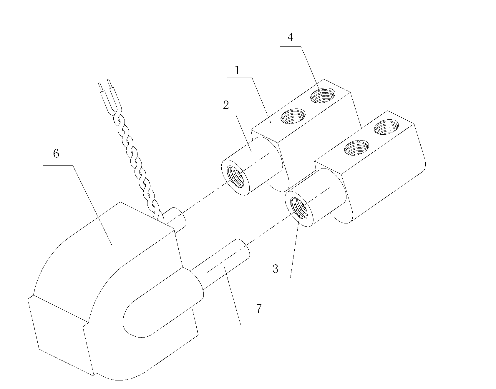
[0031] image 3 , Figure 4 , Figure 5 , Figure 6 In the shown embodiment, the connection terminal copper rod 7 of the device transformer 6 is inserted into the center of the cylindrical column 2 of the terminal button 1, and the connection hole 3 matching the connection terminal copper rod 7 of the device transformer 6 is provided. , use a press or a hydraulic press to press or hydraulically press the cylindrical column 2 of the terminal button 1, so that the material of the cylindrical column 2 is extruded and extended into the connecting hole 3, so that the cylindrical column 2 forms a hexagonal column 8 shape, and the connection The end copper rod 7 and the connection hole 3 are tightly attached to each other. Due to the stable and reliable mechanical pressing, the contact resistance is low; at the same time, after the connection hole 3 is mechanically pressed into the shape of the hexagonal column 8 by the cylindrical column 2, the connection hole 3 has become a spec...

Embodiment 3

[0034] Figure 7 , Figure 8 , Figure 9 , Figure 10 In the shown embodiment, the connecting end of the device transformer 6 and the self-holding relay 9 is inserted into the center of the cylindrical column 2 of the terminal button 1 with multi-strand flexible wires 10, and the device transformer 6, self-holding relay In the matching connecting hole 3 of the multi-strand flexible wire 10 at the connecting end of 9, press or hydraulically press or hydraulically press the cylindrical post 2 of the terminal button 1, so that the material of the cylindrical post 2 flows toward the connecting hole 3 Inner extruding extension causes cylindrical column 2 to form polygonal column 11 shape; The material is more evenly extruded and extended into the connecting hole 3, so that the multi-strand flexible wire 10 at the connecting end of the device is squeezed tightly and closely attached to the connecting hole 3; thereby further reducing the contact between the two Resistance is also...


PUM


Abstract

The invention provides a connection structure of a connection end of a component and a connection terminal used in instruments and meters, discloses the connection structure of the connection end of the component and the connection terminal which is especially suitable for the field of electric energy meters, and aims at providing the connection structure of the connection end of the component and the connection terminal which is simple in structure, low in resistance in a contact position of the connection end of the component and the connection terminal, large in axial torsion of the connection terminal and low in self-power-consumption. The connection structure of the connection end of the component and the connection terminal comprises the connection terminal and a sampling device, wherein the connection terminal is a metal connection cylinder. Two ends of the metal connection cylinder are respectively provided with opposite holes, and the opposite holes are not communicated with each other. One end of the connection terminal is provided with a connection hole used for input and output of meter external power, and the other end of the connection terminal is connected with an input and output end binding post of the component, and a compression joint structure is formed by the other end of the connection terminal and the input and output end binding post of the component. The connection structure of the connection end of the component and the connection terminal has the advantages of being simple in structure, and convenient to produce and assemble. Meanwhile, the connection structure of the connection end of the component and the connection terminal can not loose or fall off easily and can improve usability of the component and the like.

Description

technical field [0001] The present invention relates to a connection structure used for connecting terminals and terminal buttons of components in instruments and meters, current components such as control components such as transformers and self-holding relays, sampling and measuring devices; such as for communication, Fields of measurement, metering, and automation control; such as the field of electronic energy meters, especially the connection structure of connection terminals and terminal buttons of measurement, metering, control components, sampling devices, etc.; especially suitable for connection ends of components in the field of energy meters The connection structure with the terminal button. Background technique [0002] Components such as transformers, self-holding relays, and manganin electronic shunts are widely used in the fields of electronics and automation control, such as communication systems, measurement or metering components. Therefore, this type of c...

Claims


Application Information

Patent Timeline
Patent Type & Authority Applications(China)
IPC IPC(8): H01R11/11H01R4/36H01R43/16H01R43/048
Inventor 朱永虎
Owner TONGXIANG WEIDA ELECTRONICS
Why Eureka
Try Eureka