Wiring harness production method, wire supporting device, and connection-type wire retaining rod

A wire holding and supporting device technology, applied in the direction of connection, connection and connection by deformation, circuit/collector parts, etc., can solve problems such as difficult operation, and achieve the effect of increasing the ease of work

Inactive Publication Date: 2012-12-26
SUMITOMO WIRING SYST LTD
View PDF9 Cites 2 Cited by
  • Summary
  • Abstract
  • Description
  • Claims
  • Application Information

AI Technical Summary

Problems solved by technology

[0004] However, when ordinary wires and long wires are held by a single wire holding rod, the long wires may hang down by a length longer than the ordinary wires to be placed

Method used


Image

  • Wiring harness production method, wire supporting device, and connection-type wire retaining rod
  • Wiring harness production method, wire supporting device, and connection-type wire retaining rod
  • Wiring harness production method, wire supporting device, and connection-type wire retaining rod

Examples


Embodiment Construction

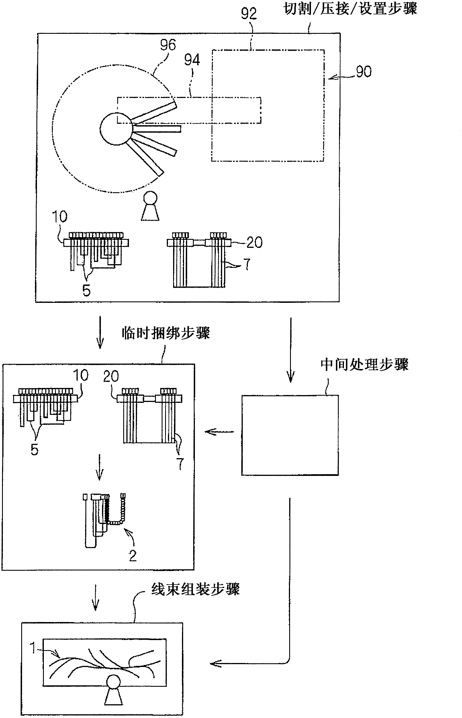
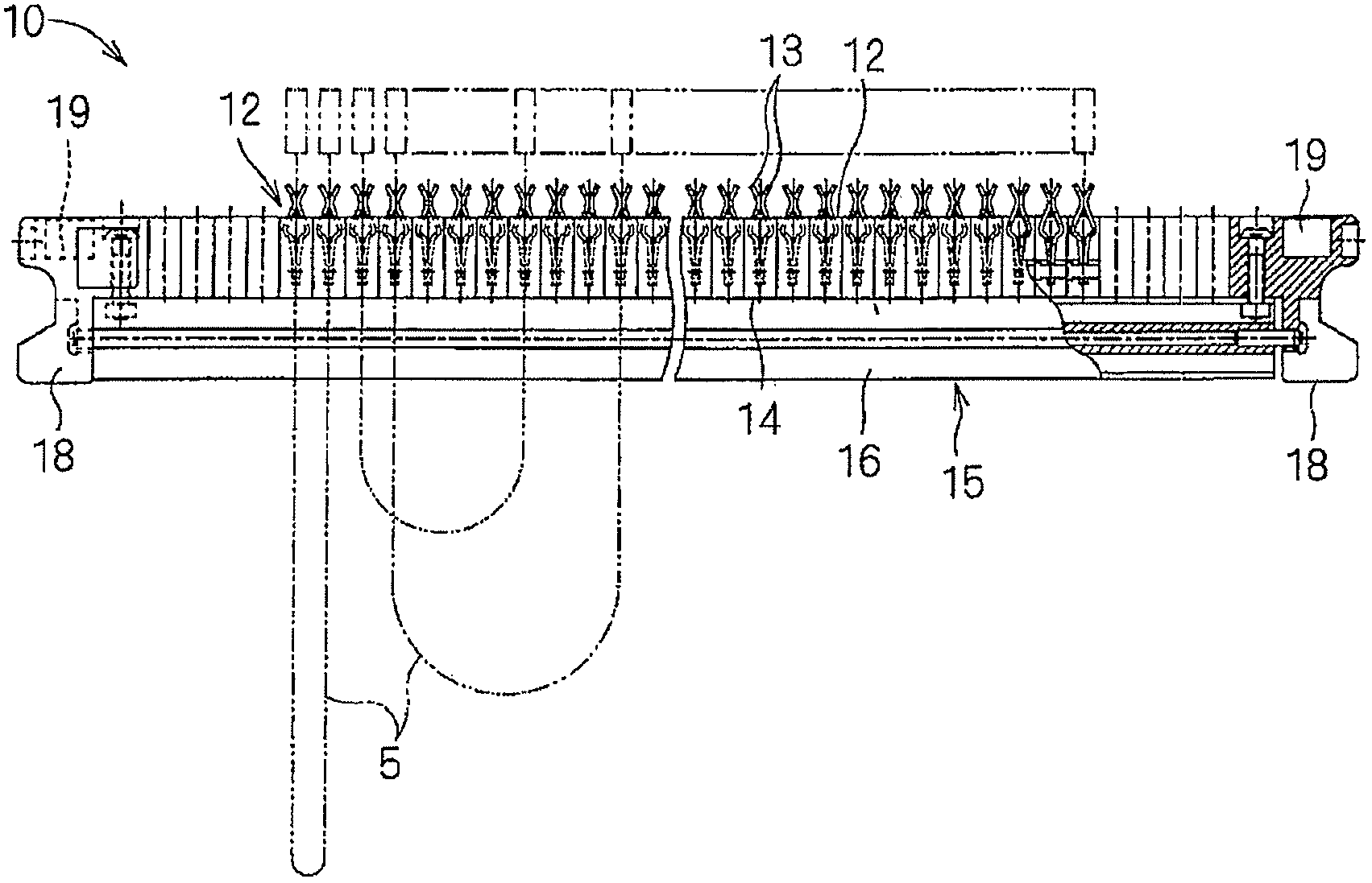
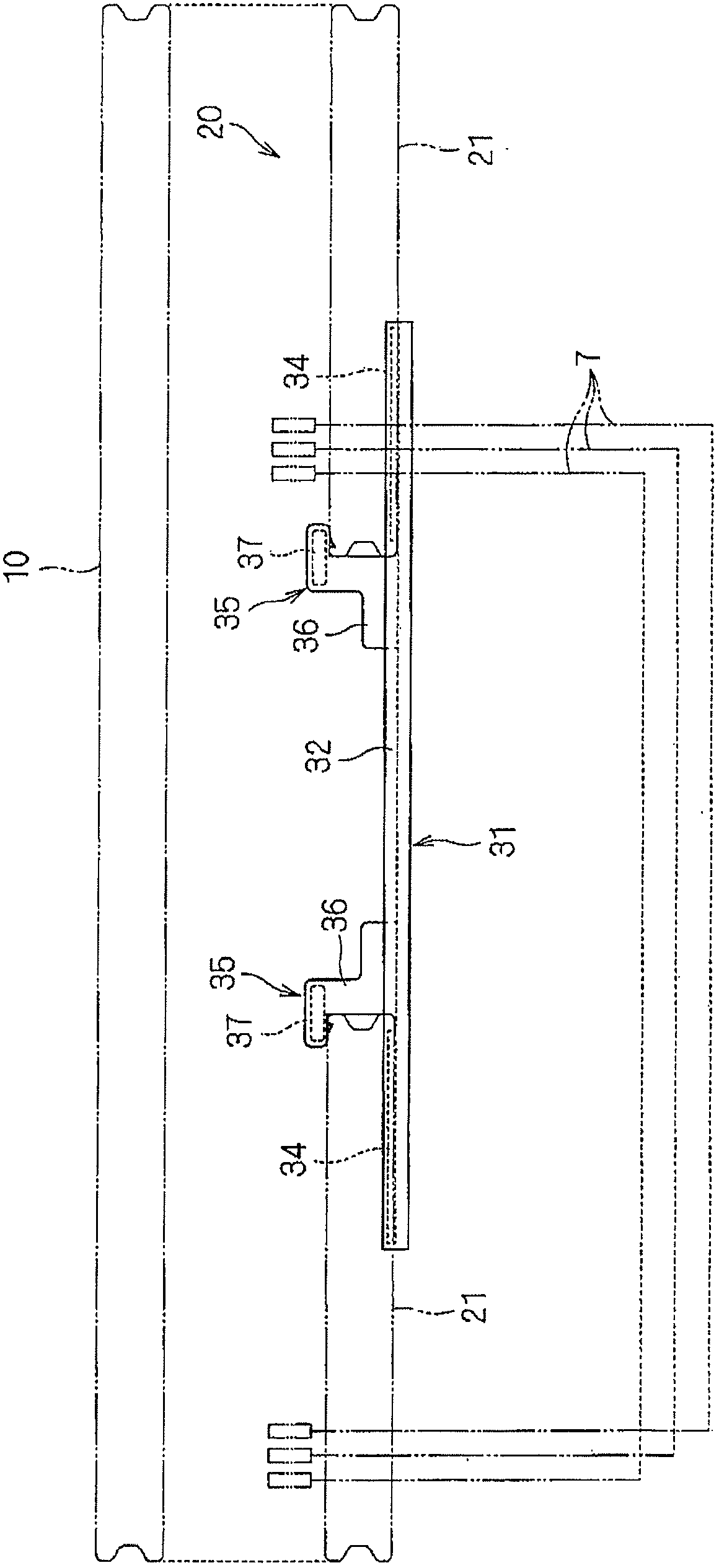
[0044] A wire harness manufacturing method, a connection type wire holding bar, and a wire supporting device will be described hereinafter according to one or more embodiments. This wire harness manufacturing method is a method of manufacturing a wire harness using a plurality of electric wires. Connection type wire retaining rods and wire support devices are used in the corresponding wire harness manufacturing process.

[0045]

[0046] The wire harness 1 is a wire harness that can be installed in, for example, an automobile, in which various electric wires for power supply, signal transmission, etc. are in a state ready for wiring (see figure 1 ) are tied together. In the manufacturing process of the wire harness 1, the temporary bundle 2 smaller than the wire harness 1 may be formed in advance by bundling a plurality of electric wires. The electric wires constituting the wire harness 1 or the temporary bundle 2 may include electric wires longer than other electric wires...


PUM


Abstract

The invention relates to a wiring harness production method used for producing a plurality of wire harnesses. The method comprises : a.) ends of a plurality of end connection common wires are disposed in a plurality of wire retaining parts in a sequential order of disassembly therefore the plurality of end connection common wires can be arranged in rows; by connecting the terminals to all the ends of the common wires in a pressing manner, the end connection common wires can be produced, and the plurality of wire retaining parts are disposed in the common wire retaining rods; b.) ends of end connection long wires are disposed in a plurality of wire retaining parts to arrange the end connection long wires in rows, and by connecting the terminals to the ends of the long wires, which are longer than the common wires, in a pressing manner to produce the end connection long wires, and the plurality of retaining parts can be formed in the long wire retaining rods; c.) the end connection common wires and the end connection long wires are bound together.

Description

technical field [0001] The present invention relates to a technique for manufacturing a wire harness. Background technique [0002] JP-A-2009-152104 discloses a method of manufacturing a wire harness using a wire holding bar provided with a plurality of wire holding portions arranged in a row. In this wire harness manufacturing method, the ends of various terminating wires are individually handled and set in the respective wire holding portions of the wire holding bar so as to be arranged in order based on the sequence of steps, by cutting the wires and pressing the terminals. Each of said terminated wires is produced by attaching to the ends of the wires. A worker handles each of the terminated electric wires provided in the electric wire holding portion by gripping the ends of the terminated electric wires. Thus, the ease of work is increased in downstream work steps. [0003] In the wire harness manufacturing method of JP-A-2009-152104, ends of various types of termina...

Claims


Application Information

Patent Timeline
IPC IPC(8): H01R43/00H01R43/04H01R43/28
Inventor 田口悠青井觉小西孝宜石木友浩
Owner SUMITOMO WIRING SYST LTD
Why Eureka
Try Eureka