
Switch device

A switchgear and ventilation device technology, which is applied in the direction of switchgear, switchgear components, substation/switchgear cooling/ventilation, etc., can solve the problems of component damage, limited air intake, inability to cool busbar room and cable room, etc. Achieve the effect of compact structure and improved cooling capacity

Active Publication Date: 2012-12-26
SIEMENS SWITCHGEAR LTD SHANGHAI
View PDF6 Cites 6 Cited by
  • Summary
  • Abstract
  • Description
  • Claims
  • Application Information

AI Technical Summary

Problems solved by technology

The disadvantage of this solution is that it only cools the handcart compartment and not the busbar and cable compartments
The disadvantages of this solution are: 1. It is still impossible to cool the cable room; 2. The fan is installed at the entrance of the only air intake channel, the air intake is limited and far away from the busbar room, which is not conducive to the cooling of the switchgear. Effective cooling; 3. When a fault such as arcing occurs in one of the two compartments of the handcart room and the busbar room, the hot high-pressure gas can enter the other compartment along with the metal particles, so that no fault occurs components in the compartment of the

Method used


Image

  • Switch device
  • Switch device
  • Switch device

Examples


Embodiment Construction

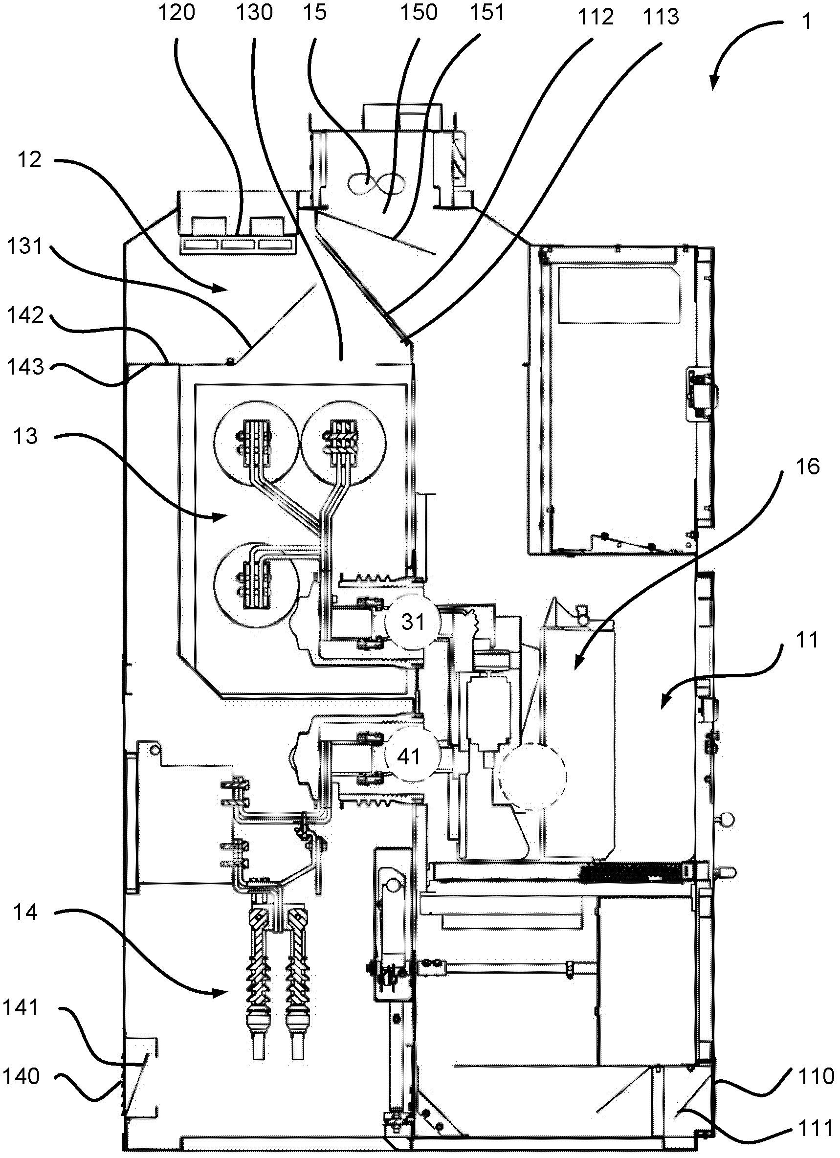
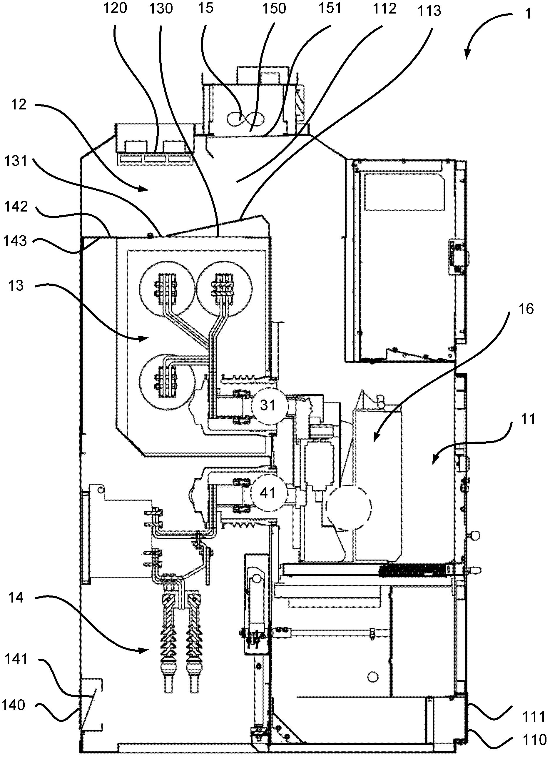
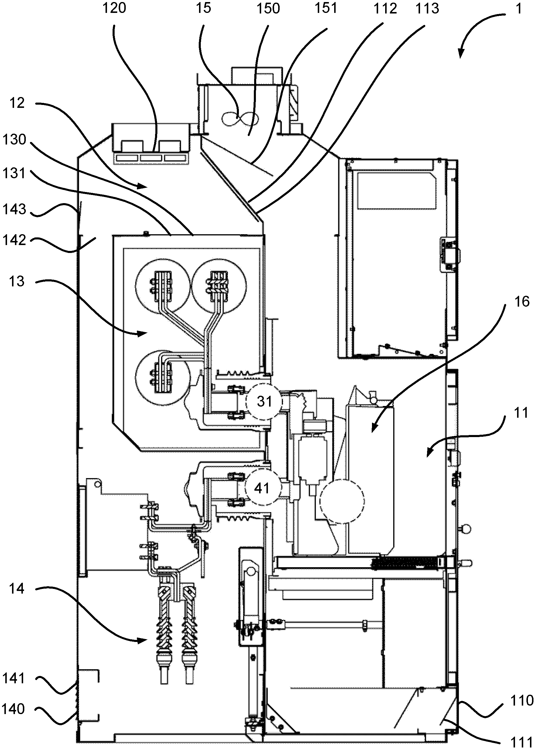
[0036] According to one embodiment of the present invention, figure 1 The switchgear 1 is in a normal operating state, wherein the handcart compartment 11 as the first compartment is adjacent to the cable compartment 14 as the second compartment and the busbar compartment 13 as the third compartment, and is adjacent to the cable compartment 14 and Between the bus compartments 13 there are respectively an interface 41 as a first interface and an interface 31 as a second interface. The handcart room 11 includes an air inlet 110 and an air outlet 150 as the first air inlet, and the ventilation device 15 is installed at the air outlet 150, wherein the air inlet 110 is preferably located on the front of the switchgear 1, and the air inlet 140 is preferably is located at the back of the switchgear 1 , while the air outlet 150 is preferably located at the top of the switchgear 1 . The cable compartment 14 includes an air inlet 140 as a second air inlet, while the busbar compartment ...


PUM


Abstract

The invention relates to a switch device. A first compartment comprises a first air inlet and an air outlet; a venting device is mounted at the air outlet; a second compartment comprises a second air inlet; and a first interface is arranged between the first compartment and the second compartment. When the venting device is in operation, air enters the first compartment and the second compartment from the first air inlet and the second air inlet respectively; the air entering the second compartment enters the first compartment through the first interface; and the air entering the first compartment is discharged out of the switch device from the air outlet. At least two of compartments such as a handcart compartment, a bus compartment and a cable compartment and the like in the switch device are subjected to forced ventilation, the corresponding compartments are provided with the air inlets, and the venting device is arranged at the air outlet, so that the cooling capability of the switch device is greatly improved.

Description

technical field [0001] The invention relates to a switchgear, in particular to a switchgear for forced ventilation of a power distribution system. Background technique [0002] Switchgear (such as switchgear) is an important equipment in the power distribution system, which usually includes compartments such as handcart room, busbar room and cable room. For a high-load switchgear, due to the high rated operating current it bears, a large amount of heat will be generated rapidly during operation, causing the temperature inside the switchgear to rise sharply. If this heat is not discharged as soon as possible, it will seriously affect the performance of various insulating components in the switchgear, and thus cause potential safety hazards. This problem is especially acute for switching devices with a compact structure and little internal space. [0003] Chinese patent CN201142530Y discloses a switchgear for forced ventilation, which has a fan installed at the air inlet of ...

Claims


Application Information

Patent Timeline
Patent Type & Authority Applications(China)
IPC IPC(8): H02B1/56H02B11/02H02B11/167
Inventor 陈涟虎姚东瑜戴立俊
Owner SIEMENS SWITCHGEAR LTD SHANGHAI
Learn More