Supercharge Your Innovation With Domain-Expert AI Agents!

Control circuit and constant current source circuit with same

A technology of control circuit and main circuit, applied in control/regulation system, high-efficiency power electronic conversion, conversion equipment with intermediate conversion to AC, etc., can solve the problems of small power factor and large total harmonic distortion of constant current source circuit , to achieve the effect of reducing total harmonic distortion, improving power factor and reducing the degree of distortion

Active Publication Date: 2014-11-26
INVENTRONICS HANGZHOU
View PDF5 Cites 0 Cited by
  • Summary
  • Abstract
  • Description
  • Claims
  • Application Information

AI Technical Summary

Problems solved by technology

[0006] However, the applicant found that: figure 1 and figure 2 The shown constant current source circuit has high total harmonic distortion (THD) and low power factor (PF)

Method used


Image

  • Control circuit and constant current source circuit with same
  • Control circuit and constant current source circuit with same
  • Control circuit and constant current source circuit with same

Examples


Embodiment Construction

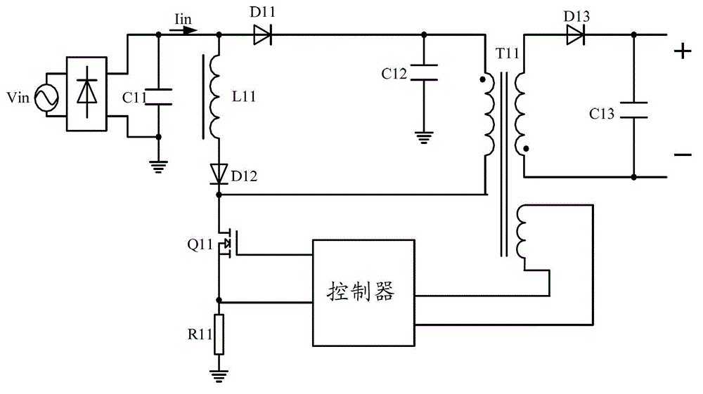
[0037] exist figure 1 In the constant current source circuit shown, when the switch tube Q11 is turned on, the input current Iin flows through the inductor L11, the second diode D12 and the switch tube Q11 in sequence, and the primary winding of the transformer T11 is powered by the second capacitor C12, and the current Iin flows The current It passing through the primary winding of the transformer T11 also flows through the switch tube Q11, and the current Is flowing through the switch tube Q11 includes the input current Iin and the primary current It of the transformer T11; when the switch tube Q11 is turned off, the inductor L11 The second capacitor C12 is charged through the second diode D12, and the transformer T11 is discharged through the secondary winding to supply power to the load.

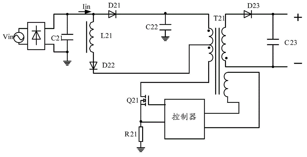
[0038] exist figure 2 In the constant current source circuit shown, when the switch tube Q21 is turned on, the input current Iin flows through the inductance L21, the second diode D22,...


PUM


Abstract

The invention discloses a control circuit used to control a main circuit in a constant current source circuit. The control circuit comprises a controller, a ripple generation circuit and a compensation circuit; the ripple generation circuit is used to obtain a voltage signal which is in a first proportion to the output voltage of a transformer in the main circuit, and separate out a ripple signal in the voltage signal; the compensation circuit is used to acquire the current sample signal of a switch tube in the main circuit, superpose and transmit the ripple signal and the current sample signal to the current sample input terminal of the controller as the current sample input signal of the controller; the controller receives the current sample input signal outputted by the compensation circuit, switches off the switch tube when the current sample input signal reaches a current threshold, and switches on the switch tube when the on-off cycle of the switch tube is in a second proportion to the duration of the current. The control circuit disclosed by the invention can reduce the total harmonic distortion of the constant current source circuit and improve the power factor of the circuit. The invention also discloses a constant current source circuit.

Description

technical field [0001] The invention relates to the technical field of constant current power supply, in particular to a control circuit and a constant current source circuit provided with the control circuit. Background technique [0002] In the field of power electronics technology, the constant current source circuit can provide a stable current for electrical equipment to drive the electrical equipment to operate stably. Due to the higher and higher requirements for power factor and harmonics of electrical equipment, in order to obtain high power factor and reduce the harmonic distortion of input current, power factor correction (PFC) technology is introduced in the constant current source circuit. figure 1 and figure 2 There are two existing constant current source circuits, including a main circuit and a controller, wherein the main circuit includes an input branch and a converter. [0003] exist figure 1 In the shown constant current source circuit, the input bran...

Claims


Application Information

Patent Timeline
Patent Type & Authority Patents(China)
IPC IPC(8): H02M3/28H02M3/335H02M1/14H02M1/42
CPCY02B70/126Y02B70/10Y02P80/10
Inventor 孙旭峰俞杭冬
Owner INVENTRONICS HANGZHOU
Features
  • R&D
  • Intellectual Property
  • Life Sciences
  • Materials
  • Tech Scout
  • Unparalleled Data Quality
  • Higher Quality Content
  • 60% Fewer Hallucinations
Learn More