
Method and device for adjusting emitted light power of optical module

A technology for emitting light and optical modules, applied in the field of optical communication, can solve problems such as the waste of emitted optical power, the distance is not exactly the same, and the power consumption of optical modules is reduced, achieving high adjustment efficiency and accuracy, expanding the scope of application, and adjusting the process simple effect

Active Publication Date: 2012-12-26
HISENSE BROADBAND MULTIMEDIA TECH
View PDF5 Cites 6 Cited by
  • Summary
  • Abstract
  • Description
  • Claims
  • Application Information

AI Technical Summary

Problems solved by technology

[0004] Generally, the same type of optical modules are set to have the same transmit optical power, and the user cannot automatically adjust according to needs
However, in the current deployment process of optical networks, the transmission distances of the same type of optical modules are not exactly the same. The waste of optical power emitted by many optical modules with short transmission distances affects the reduction of power consumption of optical modules, and makes the scope of application of optical modules narrow, and the application is limited to a certain extent

Method used


Image

  • Method and device for adjusting emitted light power of optical module
  • Method and device for adjusting emitted light power of optical module

Examples


Embodiment Construction

[0036] The technical solutions of the present invention will be further described in detail below in conjunction with the accompanying drawings and specific embodiments.

[0037] Please refer to figure 1 ,Should figure 1 A structural block diagram of an embodiment of the device for adjusting the optical power emitted by the optical module of the present invention is shown, and the direction of the arrow in the figure indicates the direction of data transmission in each unit.

[0038] like figure 1 As shown, the device for adjusting the emitted light power of the optical module in this embodiment specifically includes each unit part and the function of each part in detail as follows:

[0039] The control terminal 11 is used to send energy level data related to the transmission distance of the optical module.

[0040] The communication unit 12 is connected to the control terminal 12, and the control terminal 12 transmits energy level data related to the transmission distance ...


PUM


Abstract

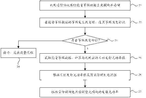
The invention discloses a method and a device for adjusting the emitted light power of an optical module. The method comprises the following steps of: (1) transmitting and storing energy level data related to the transmission distance of the optical module to the optical module by using a communication protocol; (2) acquiring the energy level data by the optical module, and calculating a target emitted light power value corresponding to the energy level data; (3) adjusting the modulation current in a closed loop way according to the target emitted light power value to acquire a corresponding actual modulation current value when the actual emitted light power value equals to the target emitted light power value; and (4) adjusting the emitted light power of the optical module according to the actual modulation current value. With the method and the device provided by the invention, the dynamic adjustment of the emitted light power of the optical module can be realized, the power consumption of the optical module is reduced, and the generality of the optical module is increased.

Description

technical field [0001] The invention belongs to the technical field of optical communication, in particular relates to the adjustment of optical module parameters, and more specifically relates to a method and a device for adjusting the emitted light power of the optical module. Background technique [0002] With the continuous expansion of the transmission capacity and the continuous improvement of the transmission rate of the main line of the communication network, the optical fiber communication has become the main transmission means of the modern information network. In the current optical communication network, such as wide area network (WAN), metropolitan area network (MAN), local area network (LAN), etc., there are more and more types of optical transceiver modules as one of the core optoelectronic devices. The main function of the optical transceiver integrated module is to realize photoelectric / electrical-optical conversion. At the transmitting end, the electrical s...

Claims


Application Information

Patent Timeline
IPC IPC(8): H04B10/12H04B10/02
Inventor 马军涛李刚林青合徐建帅王文希宋哲韬鲍晓东
Owner HISENSE BROADBAND MULTIMEDIA TECH
Learn More