A minimally invasive drilling positioning tool for spinal canal expansion

A tool and spinal canal technology, applied in the field of minimally invasive drilling positioning tools for spinal canal expansion, to achieve the effects of preventing shaking, being easy to hold by hand, and simple in structure

Active Publication Date: 2016-08-10
SUZHOU IDEAL MEDICAL APPLIANCE
View PDF7 Cites 0 Cited by
  • Summary
  • Abstract
  • Description
  • Claims
  • Application Information

AI Technical Summary

Problems solved by technology

For spinal stenosis and dilation, minimally invasive still faces many difficulties
So far, there is no surgical method and corresponding special surgical tool that can realize the minimally invasive surgery of spinal canal dilatation.

Method used


Image

  • A minimally invasive drilling positioning tool for spinal canal expansion
  • A minimally invasive drilling positioning tool for spinal canal expansion
  • A minimally invasive drilling positioning tool for spinal canal expansion

Examples


Embodiment 1

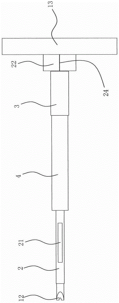
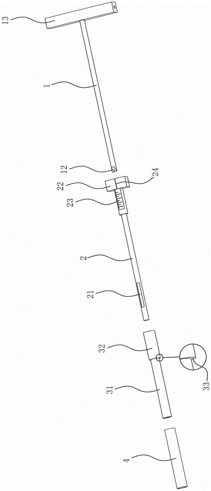
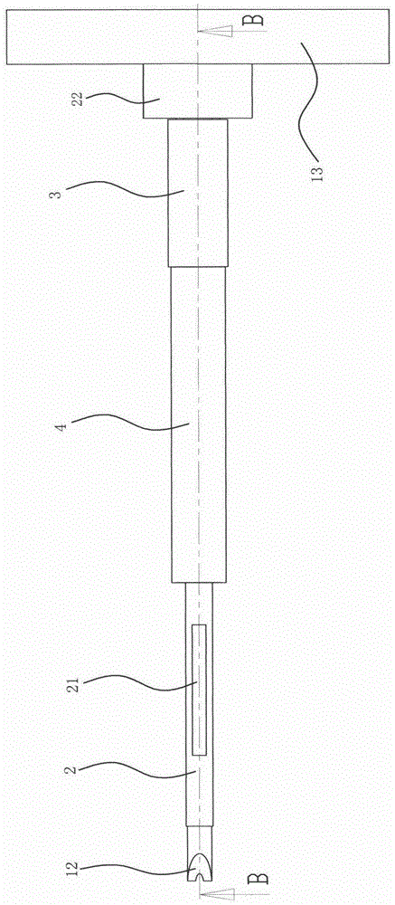
[0028] Embodiment one: if Figure 1 to Figure 4 As shown, a minimally invasive drilling positioning tool for spinal canal expansion includes a drill rod 1, a sleeve rod 2 slidingly socketed with the drill rod 1, a positioning screw sleeve 3 threadedly socketed with the sleeve rod 2, and The positioning screw sleeve 3 is matched with the fixed sleeve 4, and the drill rod 1 is provided with a through hole 11 in the axial direction. The through hole 11 is used to allow the positioning guide pin to pass through the Insert the through hole, then take out the drill pipe, and then insert the tool to be replaced through the through hole. During the replacement process, the positioning guide pin and the through hole play a positioning role, so that when the tool is replaced, the working position is always positioned constant.

[0029] The drill bit 12 of the drill rod 1 extends out of the sleeve rod 2, the length of the sleeve rod 2 is greater than the length of the positioning screw ...

Embodiment 2

[0033] Embodiment 2: On the basis of the above embodiments, the length of the fixing sleeve 4 is the same as that of the positioning screw sleeve 3, which ensures that once the fixing sleeve 4 contacts the surface of the bone, the positioning screw sleeve 3 and the sleeve rod 2 will be fixed The sleeve stops and will not continue to extend into the borehole. In addition, in order to prevent the rotating positioning screw from touching the surface of the bone when the tool is working, the length of the fixing sleeve 4 is greater than the length of the socket section 31 . The fixed sleeve 4 forms a certain distance between the socket section 31 of the positioning screw sleeve 3 and the surface of the bone.

Embodiment 3

[0034] Embodiment 3: The improvement with the above embodiment is that, as Figure 6 As shown, the fixed sleeve 4 is movably sleeved on the sleeve rod 2 and leans against the positioning screw sleeve 3 , and the positioning screw sleeve 3 is threadedly connected with the sleeve rod 2 . The difference between this solution and the above-mentioned solution is that the fixed sleeve 4 is directly placed on the sleeve rod 2 , and the rear end of the fixed sleeve 4 abuts against the positioning screw sleeve 3 . When carrying out the drilling operation, when the front end of the fixed sleeve 4 leaned against the surface of the bone, the rear end promptly leaned against the positioning screw sleeve 3, thereby preventing the positioning screw sleeve 3 and the sleeve rod 2 and the drilling rod 1 from drilling further. In comparison, this scheme has a simpler structure. The socket relationship between the fixed sleeve 4 and the positioning screw sleeve 3 is cancelled.


PUM


Abstract

The invention relates to a minimally-invasive drilling and positioning tool for treating neural canal expansion. The minimally-invasive drilling and positioning tool comprises a drill rod, a sleeve rod in sliding connection with the drill rod in a sleeved mode, a positioning screw sleeve in threaded connection with the sleeve rod in a sleeved mode and a fixing sleeve matched with the positioning screw sleeve. the drill rod is provided with a through hole along the axial direction, a drill head of the drill rod extends out of the sleeve rod, the length of the sleeve rod is larger than those of the positioning screw sleeve and the fixing sleeve, and the sleeve rod extends out of side walls of the positioning screw sleeve and the fixing sleeve to be provided with an opening. The tool is applied to new minimally-invasive dilatation of neural canal stenosis and used for cutting off, prolonging and further fixing a pedicle of a vertebral arch. A hole with the diameter of about 5mm is drilled at the patient position by applying the tool, bones are effectively isolated in drilling so that secondary trauma of human body soft tissues is avoided, and the sleeve rod, the positioning screw sleeve and the fixing sleeve are reserved and used for being effectively matched with follow-up tools in work. The wound surface of the patient is small, and minimal invasive surgery is achieved. A convalescent stage of the patient after surgery is shortened greatly, and the surgery cost is low.

Description

technical field [0001] The invention relates to a surgical medical instrument, in particular to a minimally invasive drilling positioning tool for spinal canal expansion used in spinal surgery. Background technique [0002] Spinal stenosis is one of the common diseases in middle-aged and elderly patients. Spinal stenosis is caused by bone hyperplasia in the lumbar spine itself, which causes the spinal canal to become smaller and squeezes the nerves passing through it, causing pain, inability to bend the waist, and numbness of hands and feet. , walking with a limp, etc. Spinal stenosis dilation is one of the main operations in spinal surgery. Performing spinal canal dilation requires the use of specialized surgical tools. [0003] At present, spinal stenosis dilation is an open operation. It needs to make an incision with a length of more than 10 cm on the patient's back, and then cut off and re-fix the vertebrae. This kind of open surgery has a large trauma area and damag...

Claims


Application Information

Patent Timeline
Patent Type & Authority Patents(China)
IPC IPC(8): A61B17/16A61B17/56
Inventor 杨惠林罗宗平
Owner SUZHOU IDEAL MEDICAL APPLIANCE
Why Eureka
Try Eureka