Turning processing method of wheel groove milling cutter

A technology of wheel groove milling cutter and processing method, which is applied in the field of turning processing, can solve the problem of consistent axial dimension of wheel groove milling cutter profile, achieve the effects of shortening auxiliary time, improving turning processing efficiency, and optimizing turning processing mode

Active Publication Date: 2013-01-02
HARBIN TURBINE
View PDF6 Cites 10 Cited by
  • Summary
  • Abstract
  • Description
  • Claims
  • Application Information

AI Technical Summary

Problems solved by technology

At present, there is no processing method that can ensure the consistent axial dimension of the profile line of the wheel groove milling cutter

Method used


Image

  • Turning processing method of wheel groove milling cutter
  • Turning processing method of wheel groove milling cutter
  • Turning processing method of wheel groove milling cutter

Examples


specific Embodiment approach 1

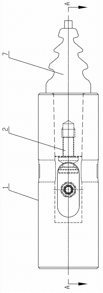
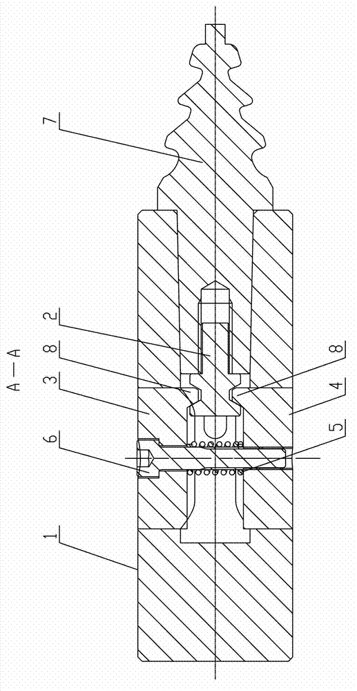
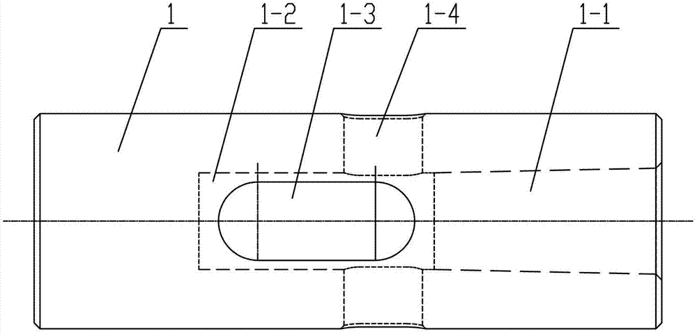
[0012] Specific implementation mode one: combine Figure 1 to Figure 13 Describe this embodiment, a wheel groove milling cutter turning fixture described in this embodiment includes a clamp body 1, a tension screw 2, an upper clamp block 3, a lower clamp block 4, a compression spring 5 and a connecting screw 6, and the clamp body 1 is Cylinder, the center of the matching end face of the clamp body 1 and the wheel slot milling cutter 7 is processed with an interconnected inner taper hole 1-1 and a cylindrical hole 1-2, and the inner taper hole 1-1 is used for positioning and assembly wheel slot milling The shank 7-1 of the knife 7, the outer surface of the clamp body 1 runs through the limiting waist hole 1-3 and the unloading waist hole 1-4 along the radial direction, and the limiting waist hole 1-3 and the unloading waist hole 1-4 is vertically arranged, and the screw rod 2-1 of tensioning screw 2 is used for being threadedly connected with the knife handle 7-1 of wheel groov...

specific Embodiment approach 2

[0013] Specific implementation mode two: combination figure 1 and figure 2 To illustrate this embodiment, the specific steps of a method for turning a wheel groove milling cutter using the jig described in Embodiment 1 described in this embodiment are as follows:

[0014] Step 1, turning and processing the wheel groove milling cutter blank on a common lathe, the lathe speed is 400r / min, the feed rate is 0.2mm / r-0.4mm / r, and the cutting depth is 1.4mm-1.6mm;

[0015] Step 2: Use the four-claw chuck on the CNC lathe to clamp the wheel groove milling cutter turning fixture, and perform alignment, and then insert one end of the tension screw 2 into the threaded hole of the wheel groove milling cutter blank, The other end of the tension screw 2 is clamped between the upper clamp block 3 and the lower clamp block 4, and the upper clamp block 3 and the lower clamp block 4 clamp the other end of the tension screw 2 through the connecting screw 6;

[0016] Step 3: Use a 55°rhombic t...

specific Embodiment approach 3

[0019] Specific implementation mode three: combination figure 1 and figure 2 To illustrate this embodiment, in Step 1 of the method for turning a wheel groove milling cutter described in this embodiment, when turning a wheel groove milling cutter blank on a common lathe, the feed rate of the lathe is 0.3mm / r, and the cutting depth is 1.5mm. Other components and connections are the same as those in the second embodiment.


PUM


Abstract

The invention discloses a turning processing method of a wheel groove milling cutter and relates to a turning processing method, in particular to a turning processing method of a wheel groove milling cutter. The turning processing method aims to solve the problem that coincident axial size of a molded line of the wheel groove milling cutter cannot be guaranteed by the existing processing method. The turning processing method comprises the following steps that the wheel groove milling cutter is processed on an engine lathe; then the wheel groove milling cutter is installed on a turning fixture, and the molded line of the wheel groove milling cutter is semi-finished by using a 55 DEG rhombic turning tool blade on a numerically controlled lathe; then the molded line of the wheel groove milling cutter is finished by using a 35 DEG rhombic turning tool blade; and after processing, the wheel groove milling cutter is taken from the turning fixture. The turning processing method is used for the turning wheel groove milling cutter.

Description

technical field [0001] The invention relates to a turning processing method, in particular to a turning processing method of a wheel groove milling cutter. Background technique [0002] The wheel groove milling cutter is a special tool for machining the wheel groove of the steam turbine rotor. The tool is used in batches. When processing the tool, it is necessary to ensure the machining accuracy and process with high efficiency to achieve the purpose of reducing costs and increasing efficiency. During processing, turning is the key and difficult point in processing the tool. When CNC turning the groove milling cutter profile, it is required that the axial dimension of the turning groove milling cutter profile must be consistent, otherwise it will increase the difficulty of subsequent processing. If the size of the molding line is different, it may even cause the workpiece to be scrapped. At present, there is no processing method that can guarantee the consistent axial dimen...

Claims


Application Information

Patent Timeline
Patent Type & Authority Applications(China)
IPC IPC(8): B23B1/00
Inventor 魏成双崔会彬魏崇巍孙盛丽
Owner HARBIN TURBINE
Why Eureka
Try Eureka