
Automobile tire pressure monitoring alarm system and control method thereof

A tire pressure monitoring and alarm system technology, applied in tire measurement, vehicle components, tire parts, etc., can solve the problem of poor stability and reliability of wireless connection signals, interruption of connection between the tire pressure monitoring device and the host, and the use of tire pressure monitoring devices Short life and other problems, to achieve the effect of rapid response, improved service life, and energy saving

Inactive Publication Date: 2015-04-08
新疆公信辉睿股权投资管理有限公司
View PDF7 Cites 0 Cited by
  • Summary
  • Abstract
  • Description
  • Claims
  • Application Information

AI Technical Summary

Problems solved by technology

[0003] In the currently used tire pressure monitoring system, the tire pressure monitoring device needs to be positioned by a locator and wirelessly connected to the host, which is troublesome to operate, and the stability and reliability of the wireless connection signal are poor, and it is easy to cause signal collusion when vehicles meet, and The transmission signal band of the car one-button start system may overlap with the wireless connection signal band, forming mutual interference, causing the connection between the tire pressure monitoring device and the host to be interrupted, and the currently used tire pressure monitoring device is powered by a battery, and the tire pressure monitoring device is installed on the tire. Inside, it is not easy to disassemble and replace the battery, and the service life of the tire pressure monitoring device is short. The tire pressure monitoring system can only monitor, but cannot effectively brake the vehicle. The monitoring results can only be displayed on the host, and remote monitoring cannot be realized.

Method used


Image

  • Automobile tire pressure monitoring alarm system and control method thereof
  • Automobile tire pressure monitoring alarm system and control method thereof

Examples


Embodiment Construction

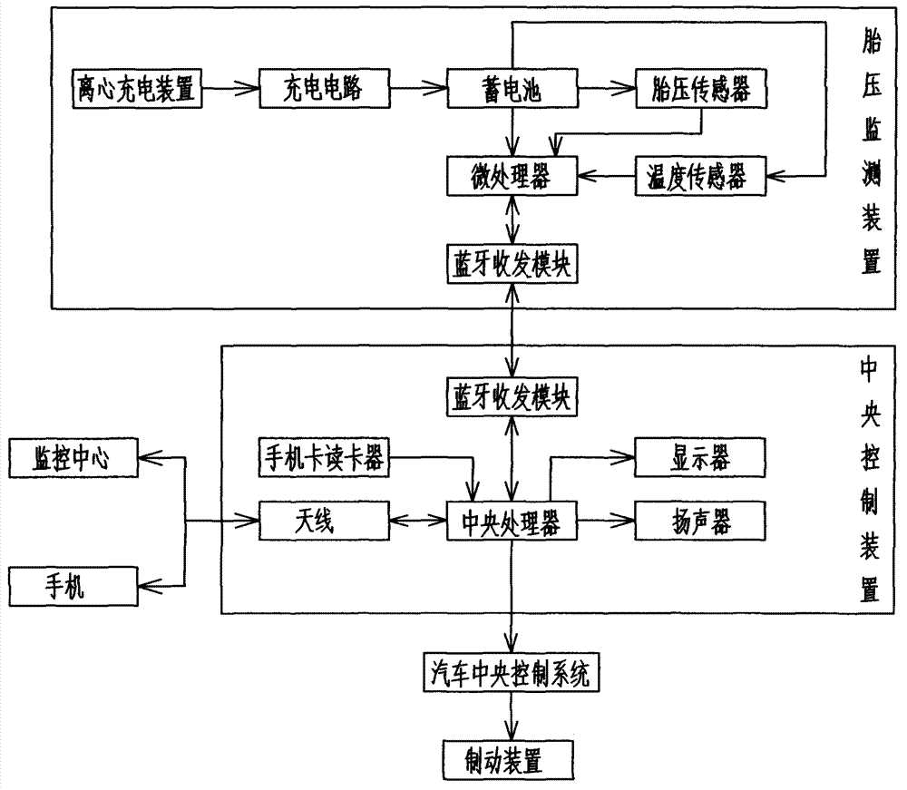
[0022] Automobile tire pressure monitoring alarm system of the present invention, as Figures 1 to 2 As shown, it includes the tire pressure monitoring device installed in the car tire and the central control device installed in the car.

[0023] The tire pressure monitoring device includes a microprocessor, a tire pressure sensor connected to the microprocessor, a temperature sensor, a battery, and a Bluetooth transceiver module. The battery supplies power for the tire pressure sensor, temperature sensor, microprocessor, and Bluetooth transceiver module. The tire pressure monitoring device The storage battery is also connected in series with a charging circuit and a centrifugal charging device in turn. The microprocessor of each tire pressure detection device is provided with a unique identification code.

[0024] The central control device includes a central processing unit, a display connected to the central processing unit, a loudspeaker, and a Bluetooth transceiver modul...


PUM


Abstract

An automobile tire pressure monitoring alarm system comprises a tire pressure monitoring device installed in the automobile tire, and a central control device installed in the automobile. The automobile tire pressure monitoring alarm system can reduce the unnecessary excessive detection as much as possible based on a comparison result of a current tire pressure and a limited pressure range, and the current automobile speed adjustment monitoring cycle, so as to save electric energy. A centrifugal charging device can charge the battery, increase use time of the system and prolong the service life. The central control device can conduct braking deceleration based on the automobile speed, has rapid response, and ensures the safety of the automobile and personnel. Bluetooth used for communicating has stable wireless signal connection, and the Bluetooth signal band is completely different from the transmission signal band of a push-button-start system of the automobile, so as to avoid communication interruption of the tire pressure monitoring device and the central control device, and guarantee usage effect. The central control device can communicate with a monitoring center and a mobile phone through the antenna, thereby realizing remote monitoring on the tire.

Description

technical field [0001] The invention relates to a detection and alarm system, in particular to an alarm system and a control method for tire pressure monitoring of automobile tires. Background technique [0002] Tires are the key components needed for the operation of automobiles. The tire pressure of automobile tires is inseparable from driving safety. If the tire pressure is too high or too low when driving at high speed, it will easily cause a tire blowout. It can cause safety hazards and cause major traffic accidents. With the development of highway construction, the speed of cars is getting faster and faster. The number of traffic accidents caused by tire blowouts is increasing. The tire pressure and temperature are detected during vehicle driving. The driver can keep abreast of the current tire working status, which can avoid or reduce the occurrence of such traffic accidents. [0003] In the currently used tire pressure monitoring system, the tire pressure monitoring...

Claims


Application Information

Patent Timeline
Patent Type & Authority Patents(China)
IPC IPC(8): B60C23/00B60C23/04B60C23/20
Inventor 张占波范守娟
Owner 新疆公信辉睿股权投资管理有限公司
Learn More